sh030051g.pdf - 第335页
13 - 34 13. SERVO AMPLIFIERS WI TH A LARGE CAPACITY ( 30k TO 55kW ) (2) Drive unit The drive unit front view shown is tha t of the MR-J3-DU30KB4, MR-J3-DU37KB4 or less. Refer to section 13.7 Outline Drawings for the appe…
13 - 33
13. SERVO AMPLIFIERS WITH A LARGE CAPACITY
(
30k TO 55kW
)
13.3.5 Connectors and signal arrangements
POINT
The pin configurations of the connectors are as viewed from the cable
connector wiring section.
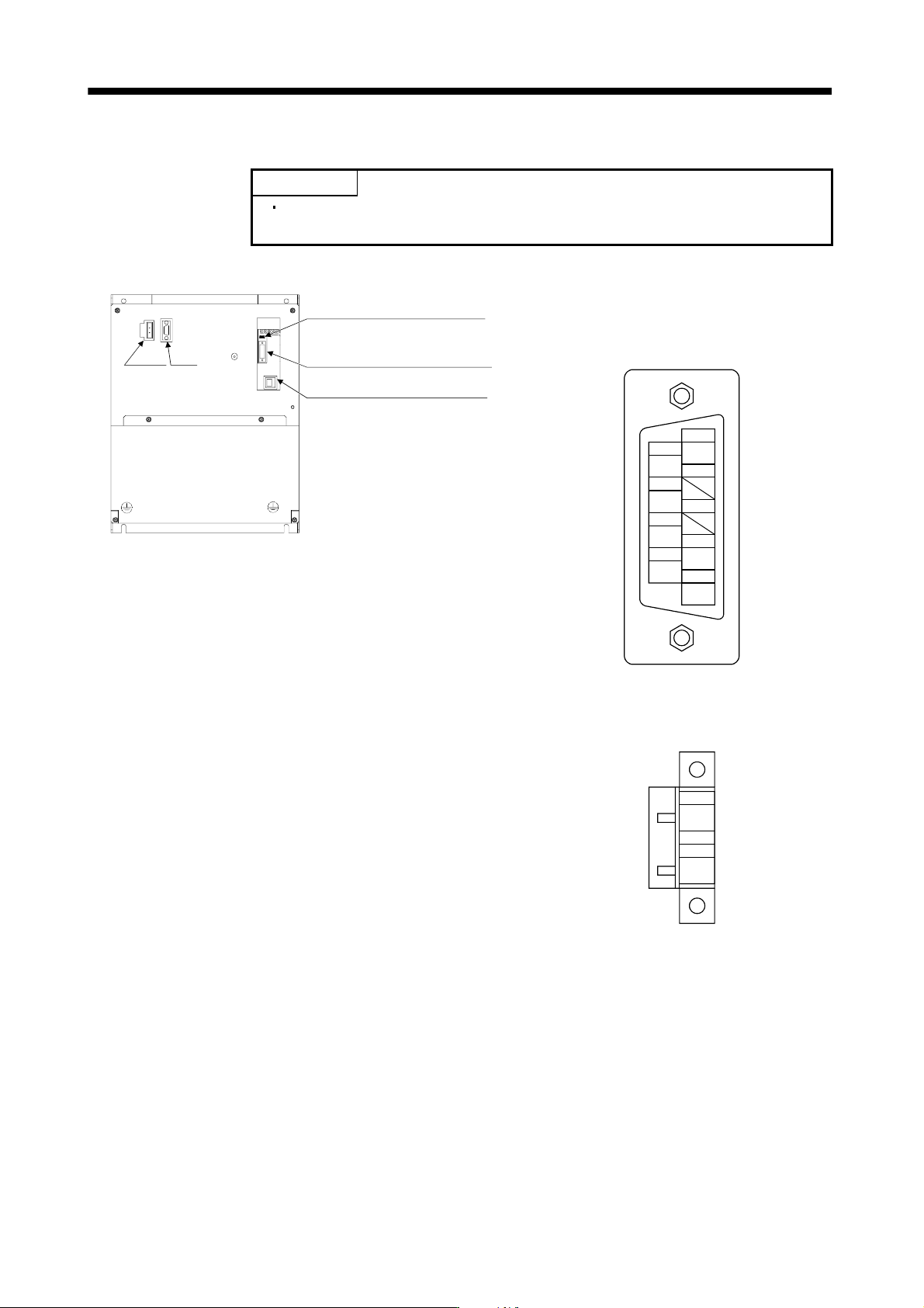
(1) Converter unit
CN6 Leave this open.
CN40 Connect to CN40A of the
drive unit.
CN3 Leave this open.
CHARGE
CNP1 CN1
CN1 (Digital I/O connector)
Model: 17JE-23090-02 (D8A) K11-CG (D-sub 9 pin or
equivalent)
(DDK)
DICOM
WNG
9
DOCOM
5
2
4
6
7
3
1
8
DOCOM
EM1
DICOM
ALM
CNP1 (Magnetic contactor wiring connector)
Model: GFKC 2.5/2-STF-7.62
(Phoenix Contact)
1
MC1
2
MC2
13 - 34
13. SERVO AMPLIFIERS WITH A LARGE CAPACITY
(
30k TO 55kW
)
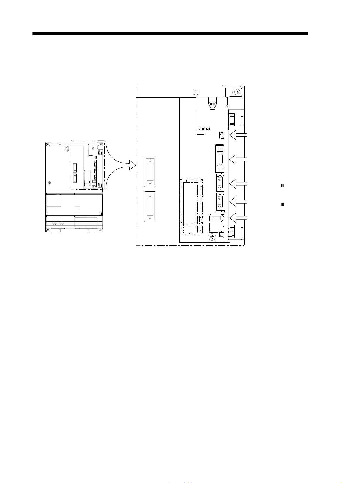
(2) Drive unit
The drive unit front view shown is that of the MR-J3-DU30KB4, MR-J3-DU37KB4 or less. Refer to section
13.7 Outline Drawings for the appearances and connector layouts of the MR-J3-DU30KB, MR-J3-DU37KB,
MR-J3-DU45KB4, MR-J3-DU55KB4.
The frames of the CN2 and CN3 connectors are
connected to the PE (earth) terminal in the amplifier.
Connector for the front axis of
CN1A SSCNET cable.
Connector for the rear axis of
CN1B SSCNET cable.
CN3 (I/O signal connector)
Refer to section 3.4.
CN5 (USB connector)
Refer to section 11.8.
CN2 (Encoder connector)
Refer to section 3.4.
13 - 35
13. SERVO AMPLIFIERS WITH A LARGE CAPACITY
(
30k TO 55kW
)
13.3.6 Converter unit signal (device) explanations
POINT
Explanations on the drive unit signals are the same as those for servo
amplifiers with 22kW or less. Refer to section 3.5.
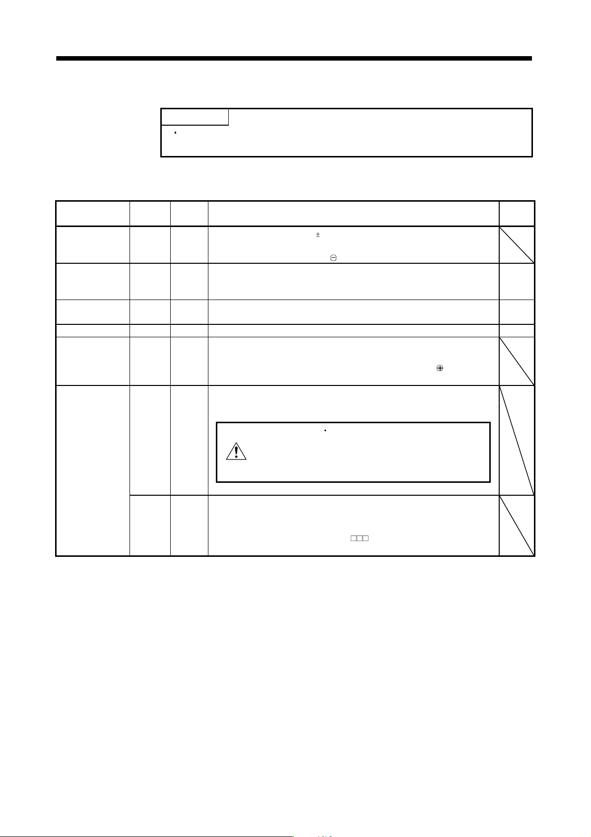
(1) Signals
For the I/O interfaces (symbols in I/O column in the table), refer to (b) of this section.
Signal name Pin code Pin No. Function/Application
I/O
division
Digital I/F power
supply input
DICOM CN1-1
CN1-6
Used to input 24VDC (24VDC 10% 150mA) for I/O interface. The power supply
capacity changes depending on the number of I/O interface points to be used.
For the source interface, connect
of 24VDC external power supply.
Forced stop EM1 CN1-7 Turn EM1 off to bring the motor to a forced stop state, in which the magnetic
connector is turned off and the servo-off signal is output to the drive unit.
Turn EM1 on in the forced stop state to reset that state.
DI
Trouble ALM CN1-2 ALM turns off when power is switched off or the protective circuit is activated.
Without alarm occurring, ALM turns on within about 1.5s after power-on.
DO
Warning WNG CN1-8 When warning has occurred, WNG turns on. DO
Digital I/F common DOCOM CN1-5
CN1-9
Common terminal for the ALM and WNG output signals of the converter unit.
Separated from LG.
Pins are connected internally. For the source interface, connect
of 24VDC
external power supply.
Magnetic contactor
drive output
MC1 CNP1-1 Connect to the operation coil of the magnetic contactor. Always supplies the
control circuit power since it is conducted with L
11
in the converter unit.
WARNING
Magnetic contactor wiring
connector on the converter unit.
Connected state may cause an
electric shock.
MC2 CNP1-2
(Note)
Connect to the operation coil of the magnetic contactor. When the converter unit
receives a start command from the drive unit, it is conducted with L
21 inside, the
control circuit power is supplied, and then the magnetic contactor is turned ON.
Change parameter No.PA02 setting to “
0” when controlling without
magnetic contactor control connector (CNP1). (Refer to section 13.3.1.)