sh030051g.pdf - 第289页
11 - 84 11. OPTIONS AND AUXILI ARY EQUIPMENT Table 11.4 Servo motor's leakage current example (Igm) Tabl e 11.5 Servo amplifier's leakage current example (Iga) Servo motor power [kW] Leakage current [mA] Servo …
11 - 83
11. OPTIONS AND AUXILIARY EQUIPMENT
11.18 Leakage current breaker
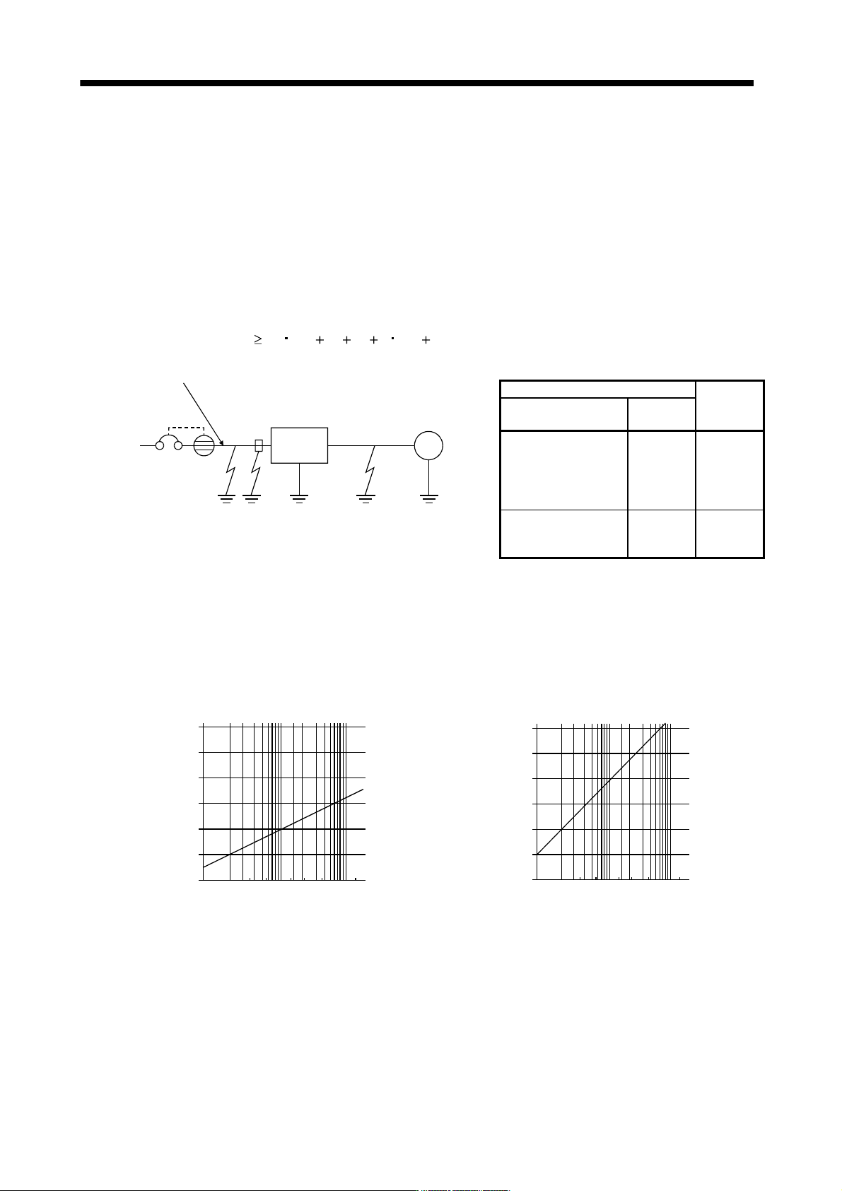
(1) Selection method
High-frequency chopper currents controlled by pulse width modulation flow in the AC servo circuits.
Leakage currents containing harmonic contents are larger than those of the motor which is run with a
commercial power supply.
Select a leakage current breaker according to the following formula, and ground the servo amplifier, servo
motor, etc. securely.
Make the input and output cables as short as possible, and also make the grounding cable as long as
possible (about 30cm) to minimize leakage currents.
Rated sensitivity current
10 {Ig1 Ign Iga K (Ig2 Igm)} [mA] (11.1)
M
Servo
amplifier
Noise
filter
NV
I
g
1I
g
nI
g
aI
g
2I
g
m
Cable
Cable
K: Constant considering the harmonic contents
Leakage current breaker
K
Type
Mitsubishi
products
Models provided with
harmonic and surge
reduction techniques
NV-SP
NV-SW
NV-CP
NV-CW
NV-L
1
General models
BV-C1
NFB
NV-L
3
Ig1: Leakage current on the electric channel from the leakage current breaker to the input terminals of the
servo amplifier (Found from Fig. 11.3.)
Ig2: Leakage current on the electric channel from the output terminals of the servo amplifier to the
servo motor (Found from Fig. 11.3.)
Ign: Leakage current when a filter is connected to the input side (4.4mA per one FR-BIF(-H))
Iga: Leakage current of the servo amplifier (Found from Table 11.5.)
Igm: Leakage current of the servo motor (Found from Table 11.4.)
120
100
80
60
40
20
0
23.5
5.5
814223880150
30 60 100
Cable size[mm
2
]
[mA]
L
e
a
k
a
g
e
c
u
r
r
e
n
t
120
100
80
60
40
20
0
2
3.5
5.5
8
14
22
38
80
150
30
60
100
Cable size[mm
2
]
[mA]
L
e
a
k
a
g
e
c
u
r
r
e
n
t
a. 200V class
b. 400V class
Fig. 11.3 Leakage current example (lg1, lg2) for CV cable run in metal conduit
11 - 84
11. OPTIONS AND AUXILIARY EQUIPMENT
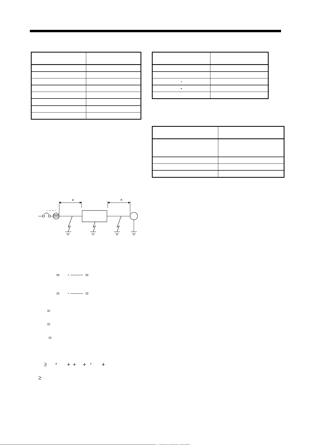
Table 11.4 Servo motor's leakage current example (Igm) Table 11.5 Servo amplifier's leakage current example (Iga)
Servo motor power
[kW]
Leakage current
[mA]
Servo amplifier capacity
[kW]
Leakage current
[mA]
0.05 to 1 0.1
0.1 to 0.6 0.1
2 0.2
0.75 to 3.5 (Note) 0.15
3.5 0.3
5 7 2
5 0.5
11 15 5.5
7 0.7
22 7
11 1.0
Note. For the 3.5kW of 400V class, leakage current is 2mA,
which is the same as for 5kW and 7kW.
15 1.3
22 2.3
Table 11.6 Leakage circuit breaker selection example
Servo amplifier
Rated sensitivity current of leakage
circuit breaker [mA]
MR-J3-10B to MR-J3-350B
MR-J3-10B1 to MR-J3-40B1
MR-J3-60B4 to MR-J3-350B4
15
MR-J3-500B(4) 30
MR-J3-700B(4) 50
MR-J3-11KB(4) to MR-J3-22KB(4) 100
(2) Selection example
Indicated below is an example of selecting a leakage current breaker under the following conditions.
M
NV
Ig1 Iga Ig2 Igm
Servo
amplifier
MR-J3-40B
2mm
2
5m 2mm
2
5m
Servo motor
HF-KP43
Use a leakage current breaker generally available.
Find the terms of Equation (11.1) from the diagram.
Ig1
20
1000
5
0.1
[mA]
Ig2
20
1000
5
0.1
[mA]
Ign
0 (not used)
Iga
0.1 [mA]
Igm
0.1 [mA]
Insert these values in Equation (11.1).
Ig
10 {0.1 0 0.1 1 (0.1 0.1)}
4.0 [mA]
According to the result of calculation, use a leakage current breaker having the rated sensitivity current (Ig)
of 4.0[mA] or more. A leakage current breaker having Ig of 15[mA] is used with the NV-SP/SW/CP/CW/HW
series.
11 - 85
11. OPTIONS AND AUXILIARY EQUIPMENT
11.19 EMC filter (recommended)
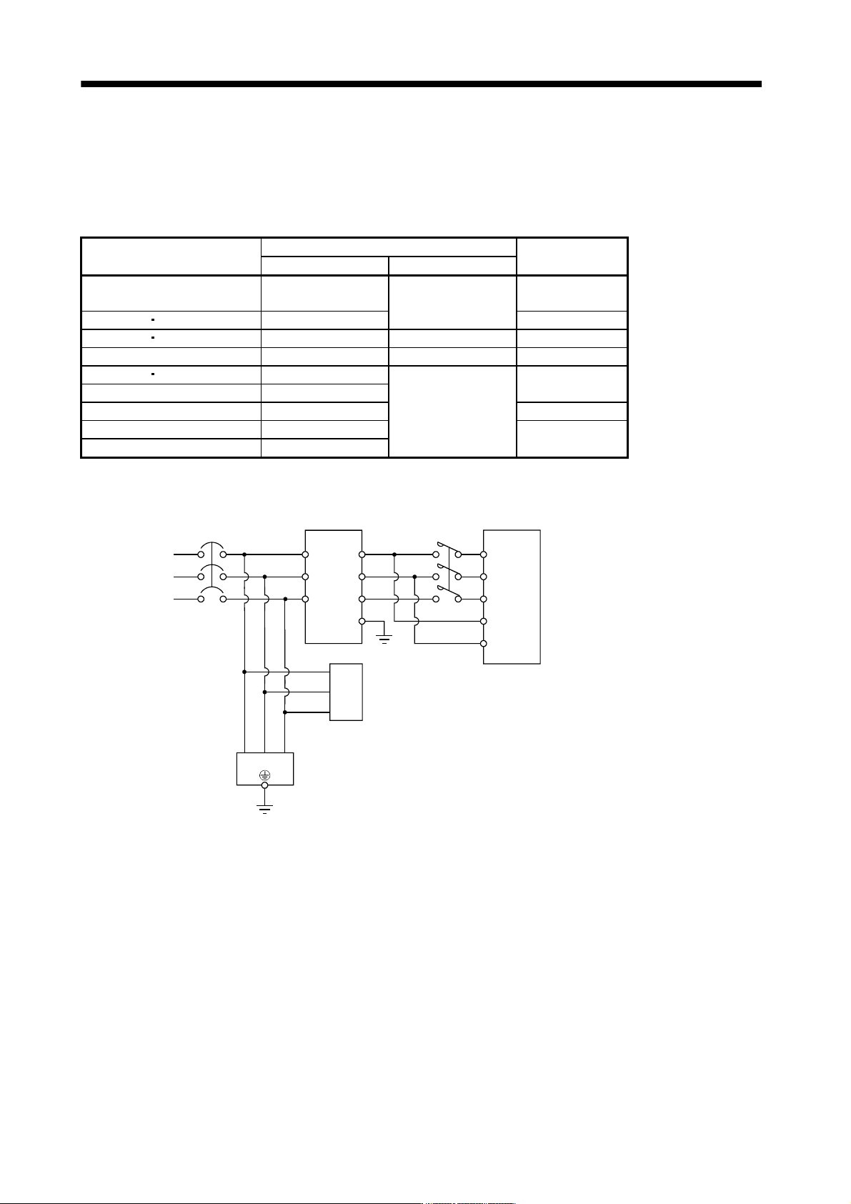
For compliance with the EMC directive of the EN Standard, it is recommended to use the following filter. Some
EMC filters are large in leakage current.
(1) Combination with the servo amplifier
Servo amplifier
Recommended filter (Soshin Electric)
Mass [kg]([lb])
Model Leakage current [mA]
MR-J3-10B to MR-J3-100B
MR-J3-10B1 to MR-J3-40B1
(Note) HF3010A-UN
5
3 (6.61)
MR-J3-250B MR-J3-350B (Note) HF3030A-UN 5.5 (12.13)
MR-J3-500B MR-J3-700B (Note) HF3040A-UN 1.5 6.0 (13.23)
MR-J3-11KB to MR-J3-22KB (Note) HF3100A-UN 6.5 15 (33.07)
MR-J3-60B4 MR-J3-100B4 TF3005C-TX
5.5
6(13.23)
MR-J3-200B4 to MR-J3-700B4 TF3020C-TX
MR-J3-11KB4 TF3030C-TX 7.5(16.54)
MR-J3-15KB4 TF3040C-TX
12.5(27.56)
MR-J3-22KB4 TF3060C-TX
Note. A surge protector is separately required to use any of these EMC filters.
(2) Connection example
L
1
L2
L3
L11
L21
Servo amplifier
1
2
3
4
5
6
E
MC
(Note 2)
Surge protector 1
(RAV-781BYZ-2)
(OKAYA Electric Industries Co., Ltd.)
(Note 2)
Surge protector 2
(RAV-781BXZ-4)
(OKAYA Electric Industries Co., Ltd.)
NFB
(Note 1)
Power supply
1
2
3
123
EMC filter
Note 1. For 1-phase 200V to 230VAC power supply, connect the power supply to L1,L2 and leave L3 open.
There is no L
3 for 1-phase 100 to 120VAC power supply. Refer to section 1.3 for the power supply specification.
2. The example is when a surge protector is connected.