sh030051g.pdf - 第40页
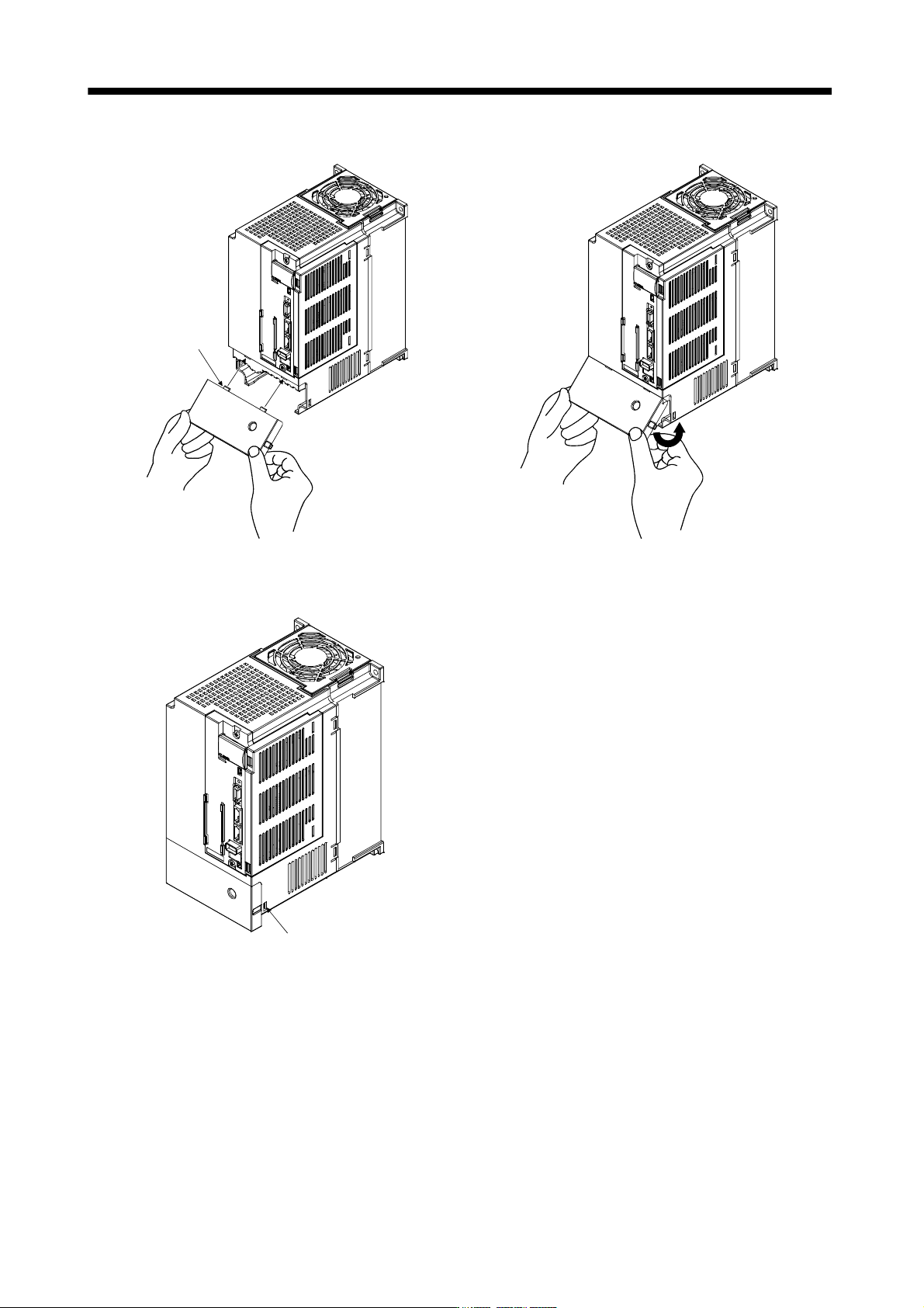
1 - 19 1. FUNCTIONS AND CONFIGURATIO N Reinstallation of the front co ver Front cove r setting ta b A) A) Insert the fron t cover setting tabs into the sockets of servo amplifier (2 places). Pull up the cover, supporting…
1 - 18
1. FUNCTIONS AND CONFIGURATION
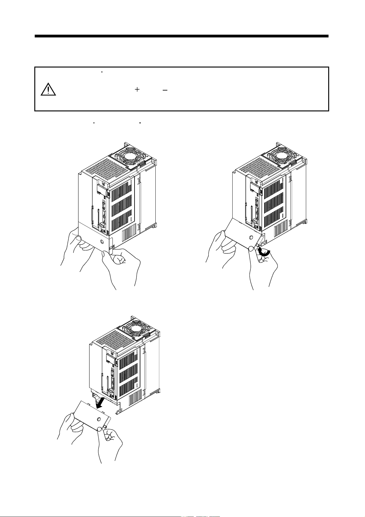
1.7.2 Removal and reinstallation of the front cover
WARNING
Before removing or installing the front cover, turn off the power and wait for 15
minutes or more until the charge lamp turns off. Then, confirm that the voltage
between P(
) and N( ) is safe with a voltage tester and others. Otherwise, an
electric shock may occur. In addition, always confirm from the front of the servo
amplifier whether the charge lamp is off or not.
(1) For MR-J3-350B4
MR-J3-500B(4) MR-J3-700B(4)
Removal of the front cover
A)
A)
Hold the ends of lower side of the front cover with
both hands.
Pull up the cover, supporting at point
A)
.
Pull out the front cover to remove.
1 - 19
1. FUNCTIONS AND CONFIGURATION
Reinstallation of the front cover
Front cover
setting tab
A)
A)
Insert the front cover setting tabs into the sockets of
servo amplifier (2 places).
Pull up the cover, supporting at point
A)
.
Setting tab
Push the setting tabs until they click.
1 - 20
1. FUNCTIONS AND CONFIGURATION
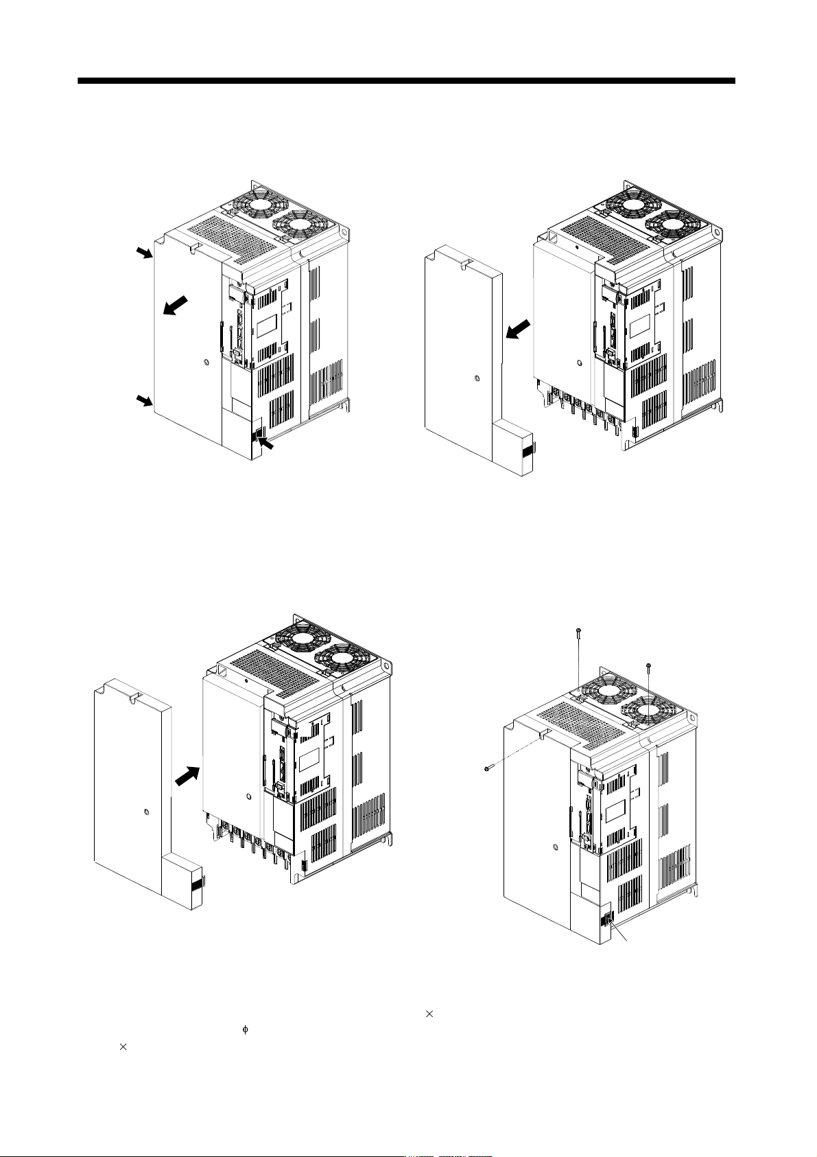
(2) For MR-J3-11KB(4) to MR-J3-22KB(4)
Removal of the front cover
A)
B)
C)
1) Press the removing knob on the lower side of the
front cover ( A) and B) ) and release the installation
hook.
2) Press the removing knob of C) and release the
external hook.
3) Pull it to remove the front cover.
Reinstallation of the front cover
A)
B)
C)
D)
Installation hoo
k
(Note 1)
(Note 1)
(Note 2)
1) Fit the front cover installation hooks on the sockets
of body cover ( A) to D) ) to reinstall it.
2) Push the front cover until you hear the clicking
noise of the installation hook.
Note 1. The cooling fan cover can be locked with enclosed screws (M4 40).
2. By drilling approximately
4 of a hole on the front cover, the front cover can be locked on the body with an enclosed screw (M4
14).