sh030051g.pdf - 第273页
11 - 68 11. OPTIONS AND AUXILI ARY EQUIPMENT (a) When using the 600V Polyvinyl chloride insulated wire (IV wire) Selection example of wire s ize when using IV wires is indicated be low. Table 11.1 Wire size select ion ex…
11 - 67
11. OPTIONS AND AUXILIARY EQUIPMENT
11.11 Selection example of wires
POINT
Refer to section 11.1.5 for SSCNET cable.
Wires indicated in this section are separated wires. When using a cable for
power line (U, V, and W) between the servo amplifier and servo motor, use a
600V grade EP rubber insulated chloroprene sheath cab-tire cable (2PNCT).
For selection of cables, refer to appendix 6.
To comply with the UL/C-UL (CSA) Standard, use UL-recognized copper
wires rated at 60
(140 ) or more for wiring. To comply with other
standards, use a wire that is complied with each standard
Selection condition of wire size is as follows.
Construction condition: One wire is constructed in the air
Wire length: 30m or less
(1) Wires for power supply wiring
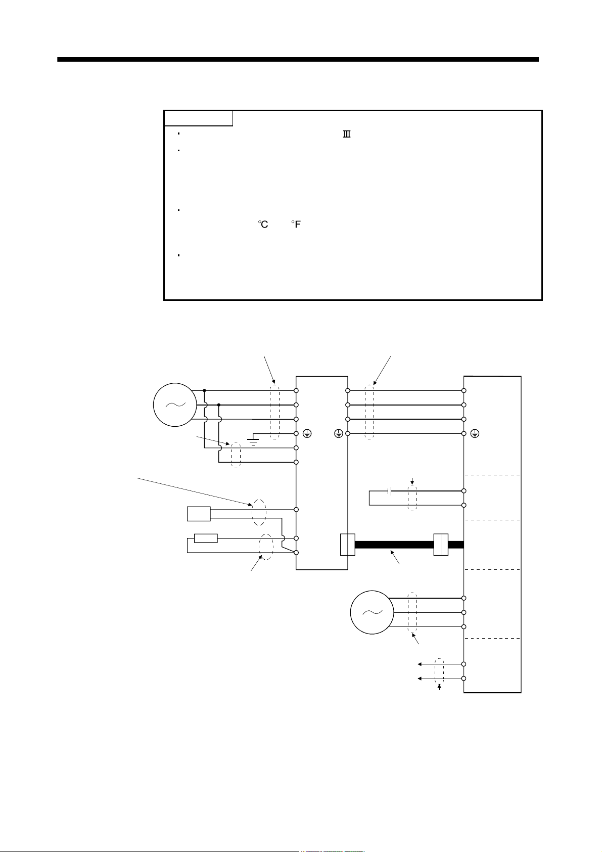
The following diagram shows the wires used for wiring. Use the wires given in this section or equivalent.
C
P
U
V
W
L
11
L21
U
V
W
L
1
L
2
L3
B1
B2
1) Main circuit power supply lead
Servo amplifier
3) Motor power supply lead
Servo motor
Power supply
Motor
Electro-
magnetic
brake
Encoder
4) Electromagnetic
brake lead
Encoder cable
2) Control power supply lead
(Note)
C
P
N
Regenerative option
4) Regenerative option lead
Cooling fan
BU
BV
BW
6) Cooling fan lead
Power supply
7) Thermal
OHS1
OHS2
Thermal
8) Power regeneration
converter lead
Power regeneration
converter
Note. There is no L
3
for 1-phase 100 to 120VAC power supply.
11 - 68
11. OPTIONS AND AUXILIARY EQUIPMENT
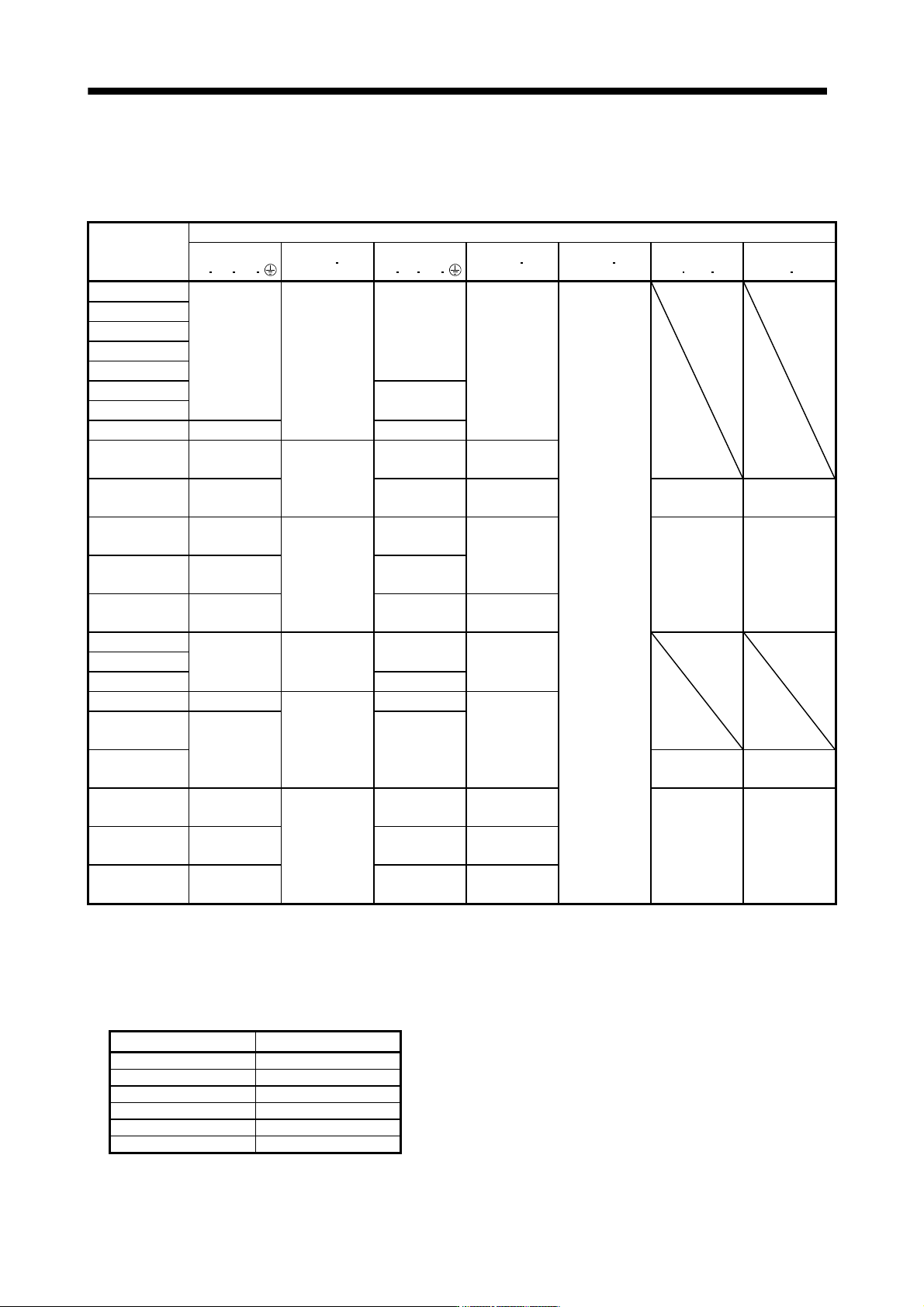
(a) When using the 600V Polyvinyl chloride insulated wire (IV wire)
Selection example of wire size when using IV wires is indicated below.
Table 11.1 Wire size selection example 1 (IV wire)
Servo amplifier
Wires [mm
2
] (Note 1, 4)
1)
L
1 L2 L3
2) L11 L21
3)
U
V W
4) P C 5) B1 B2
6)
BU
BV BW
7)
OHS1 OHS2
MR-J3-10B(1)
MR-J3-20B(1)
MR-J3-40B(1) 1.25(AWG16)
MR-J3-60B 2(AWG14)
1.25(AWG16)
2(AWG14)
MR-J3-70B
MR-J3-100B
2(AWG14)
MR-J3-200B
MR-J3-350B 3.5(AWG12) 3.5(AWG12)
MR-J3-500B
(Note 2)
5.5(AWG10): a
1.25(AWG16):
h
5.5(AWG10): a 2(AWG14): g
MR-J3-700B
(Note 2)
8(AWG8): b 8(AWG8): b 3.5(AWG12): a
2(AWG14)
(Note 3)
1.25(AWG16)
(Note 3)
MR-J3-11KB
(Note 2)
14(AWG6): c 22(AWG4): d
5.5(AWG10): j 1.25(AWG16)
MR-J3-15KB
(Note 2)
22(AWG4): d
1.25(AWG16):
g
30(AWG2): e 2(AWG14) 1.25(AWG16)
MR-J3-22KB
(Note 2)
50(AWG1/0):
f
60(AWG2/0): f 5.5(AWG10): k
MR-J3-60B4
1.25(AWG16)
MR-J3-100B4 2(AWG14) 1.25(AWG16) 2(AWG14)
MR-J3-200B4 2(AWG14)
MR-J3-350B4 2(AWG14): g
1.25(AWG16):
h
2(AWG14): g
2(AWG14): g
MR-J3-500B4
(Note 2)
5.5(AWG10): a 5.5(AWG10): a
MR-J3-700B4
(Note 2)
2(AWG14)
(Note 3)
1.25(AWG16)
(Note 3)
MR-J3-11KB4
(Note 2)
8(AWG8): l 8(AWG8): l 3.5(AWG12): j
MR-J3-15KB4
(Note 2)
14(AWG6): c
1.25(AWG16):
g
22(AWG4): d 5.5(AWG10): j 2(AWG14) 1.25(AWG16)
MR-J3-22KB4
(Note 2)
14(AWG6): m 22(AWG4): n 5.5(AWG10): k
Note 1. Alphabets in the table indicate crimping tools. For crimping terminals and applicable tools, refer to (1) (c) in this section.
2. When connecting to the terminal block, be sure to use the screws which are provided with the terminal block.
3. For the servo motor with a cooling fan.
4. Wires are selected based on the highest rated current among combining servo motors.
Use wires 8) of the following sizes with the power regeneration converter (FR-RC-(H)).
Model Wires[mm
2
]
FR-RC-15K 14(AWG6)
FR-RC-30K 14(AWG6)
FR-RC-55K 22(AWG4)
FR-RC-H15K 14(AWG6)
FR-RC-H30K 14(AWG6)
FR-RC-H55K 14(AWG6)
11 - 69
11. OPTIONS AND AUXILIARY EQUIPMENT
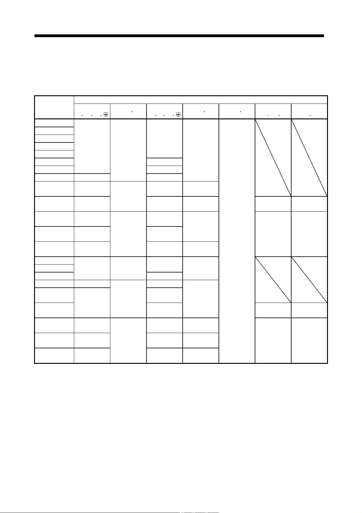
(b) When using the 600V Grade heat-resistant polyvinyl chloride insulated wire (HIV wire)
Selection example of wire size when using HIV wires is indicated below. For the wire (8)) for power
regeneration converter (FR-RC-(H)), use the IV wire indicated in (1) (a) in this section.
Table 11.2 Wire size selection example 2 (HIV wire)
Servo amplifier
Wires [mm
2
] (Note 1, 4)
1)
L
1 L2 L3
2) L11 L21
3)
U
V W
4) P C 5) B1 B2
6)
BU
BV BW
7)
OHS1 OHS2
MR-J3-10B(1)
MR-J3-20B(1)
MR-J3-40B(1) 1.25(AWG16)
MR-J3-60B 2(AWG14)
1.25(AWG16)
2(AWG14)
MR-J3-70B
MR-J3-100B 1.25(AWG16)
MR-J3-200B 2(AWG14)
MR-J3-350B 3.5(AWG12) 3.5(AWG12)
MR-J3-500B
(Note 2)
5.5(AWG10): a
1.25(AWG16):
h
5.5(AWG10): a 2(AWG14): g
MR-J3-700B
(Note 2)
8(AWG8): b 8(AWG8): b 2(AWG14): g
1.25(AWG16)
(Note 3)
1.25(AWG16)
(Note 3)
MR-J3-11KB
(Note 2)
14(AWG6): c 14(AWG6): c
3.5(AWG12): j 1.25(AWG16)
MR-J3-15KB
(Note 2)
22(AWG4): d
1.25(AWG16):
g
22(AWG4): d 1.25(AWG16) 1.25(AWG16)
MR-J3-22KB
(Note 2)
38(AWG1): p 38(AWG1): p 5.5(AWG10): k
MR-J3-60B4
1.25(AWG16)
MR-J3-100B4 2(AWG14) 1.25(AWG16) 2(AWG14)
MR-J3-200B4 2(AWG14)
MR-J3-350B4 2(AWG14): g
1.25(AWG16):
h
2(AWG14): g
2(AWG14): g
MR-J3-500B4
(Note 2)
3.5(AWG12): a
3.5(AWG12): a
MR-J3-700B4
(Note 2)
5.5(AWG10): a
1.25(AWG16)
(Note 3)
1.25(AWG16)
(Note 3)
MR-J3-11KB4
(Note 2)
5.5(AWG10): j 8(AWG8): l 2(AWG14): q
MR-J3-15KB4
(Note 2)
8(AWG8): l
1.25(AWG16):
g
14(AWG6): c 3.5(AWG12): j 1.25(AWG16) 1.25(AWG16)
MR-J3-22KB4
(Note 2)
14(AWG6): m 14(AWG6): m 3.5(AWG12): k
Note 1. Alphabets in the table indicate crimping tools. For crimping terminals and applicable tools, refer to (1) (c) in this section.
2. When connecting to the terminal block, be sure to use the screws which are provided with the terminal block.
3. For the servo motor with a cooling fan.
4. Wires are selected based on the highest rated current among combining servo motors.