sh030051g.pdf - 第22页
1 - 1 1. FUNCTIONS AND CONFIGURATION 1. FUNCTIONS AND CONFIGURATION 1.1 Introduction The Mitsubishi MELSERVO-J3 series general-purpose AC servo has further higher performance and higher functions compared to the c urrent…

6
MEMO

1 - 1
1. FUNCTIONS AND CONFIGURATION
1. FUNCTIONS AND CONFIGURATION
1.1 Introduction
The Mitsubishi MELSERVO-J3 series general-purpose AC servo has further higher performance and higher
functions compared to the current MELSERVO-J2-Super series.
The MR-J3-B servo amplifier connects to servo system controller and others via high speed synchronous
network and operates by directly reading position data. The rotation speed/direction control of servo motor and
the high accuracy positioning are executed with the data from command module. SSCNET
equipped by the
MR-J3-B servo amplifier greatly improved its communication speed and noise tolerance by adopting optical
communication system compared to the current SSCNET. For wiring distance, 50m of the maximum distance
between electrodes is also offered.
The torque limit with clamping circuit is put on the servo amplifier in order to protect the power transistor of
main circuit from the overcurrent caused by rapid acceleration/deceleration or overload. In addition, torque limit
value can be changed to desired value in the controller.
As this new series has the USB communication function, a MR Configurator-installed personal computer or the
like can be used to perform parameter setting, test operation, status display monitoring, gain adjustment, etc.
With real-time auto tuning, you can automatically adjust the servo gains according to the machine.
The MELSERVO-J3 series servo motor is with an absolute position encoder which has the resolution of
262144 pulses/rev to ensure more accurate control as compared to the MELSERVO-J2-Super series. Simply
adding a battery to the servo amplifier makes up an absolute position detection system. This makes home
position return unnecessary at power-on or alarm occurrence by setting a home position once.
1 - 2
1. FUNCTIONS AND CONFIGURATION
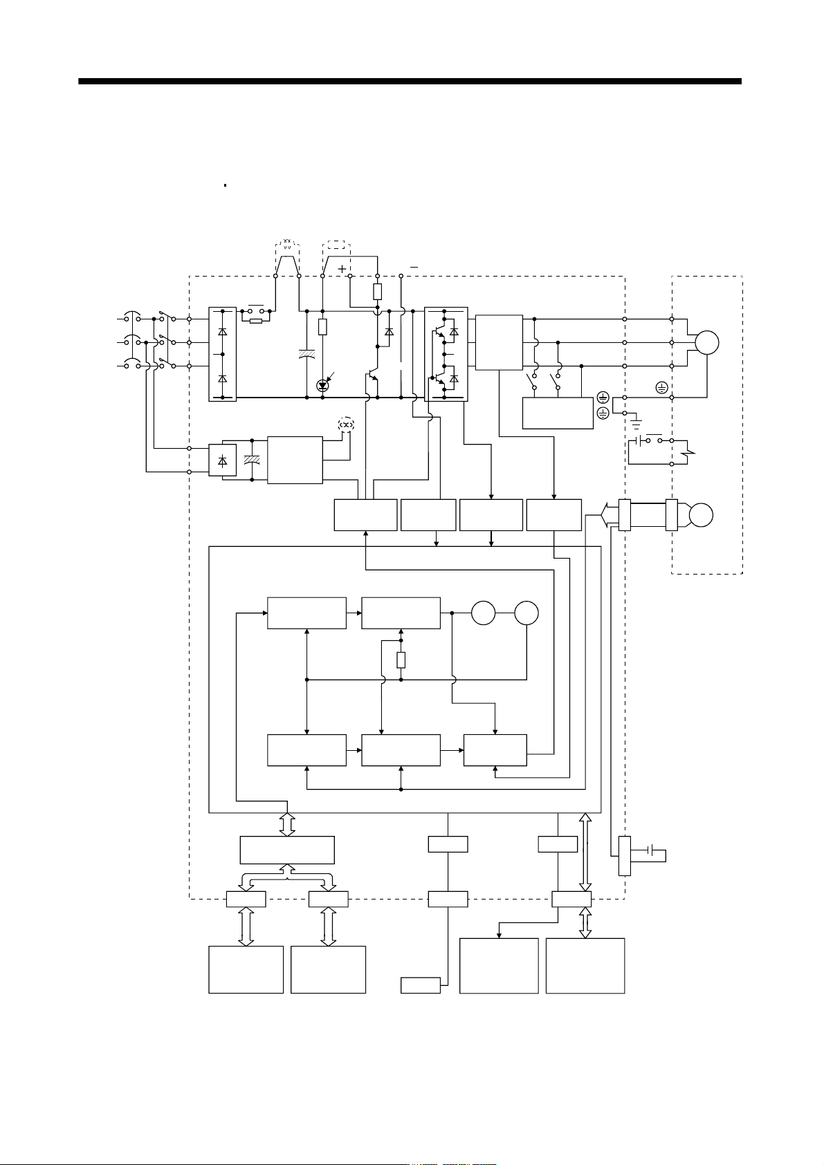
1.2 Function block diagram
The function block diagram of this servo is shown below.
(1) MR-J3-350B or less
MR-J3-200B4 or less
Base
amplifier
CN4
N( )
DC
Encoder
Current
detection
CN5
NFB MC
L
1
L
2
L
3
L
11
L
21
B2
U
V
W
B1
USB
USB
Power factor
improving DC
reactor
Regenerative
option
MR-J3BAT
P
1
P
2
D/A
Position
command
input
(Note 1)
(Note 2)
Power
supply
CHARGE
lamp
Regene-
rative
TR
Current
detector
Dynamic
brake
Electro-
magnetic
brake
Servo motorServo amplifier
Optional battery
(for absolute position
detection system)
Overcurrent
protection
Voltage
detection
Virtual
encoder
Virtual
motor
Model
torque
Personal
computer
Actual speed
control
Actual position
control
(Note 3)Cooling fan
Control
circuit
power
supply
Model position
control
Model
position
Model
speed
CN2
P( )
U
V
W
M
Model speed
control
Current
control
I/F Control
CN1BCN1A
Controller or
servo amplifier
Servo amplifier
or cap
Analog monitor
(2 channels)
CN3
Digital I/O
control
Diode
stack
Relay
RA
24VDC
Note 1. The built-in regenerative resistor is not provided for the MR-J3-10B (1).
2. For 1-phase 200 to 230VAC, connect the power supply to L
1, L2 and leave L3 open.
There is no L
3 for 1-phase 100 to 120VAC power supply. Refer to section 1.3 for the power supply specification.
3. Servo amplifiers MR-J3-70B or greater have a cooling fan.