sh030051g.pdf - 第338页
13 - 37 13. SERVO AMPLIFIERS WI TH A LARGE CAPACITY ( 30k TO 55kW ) 13.3.7 Timing chart (1) Power circuit timing chart Power-on procedure (a) Always wire the power s upply as shown in above section 13 .3.2 using the magn…
13 - 36
13. SERVO AMPLIFIERS WITH A LARGE CAPACITY
(
30k TO 55kW
)
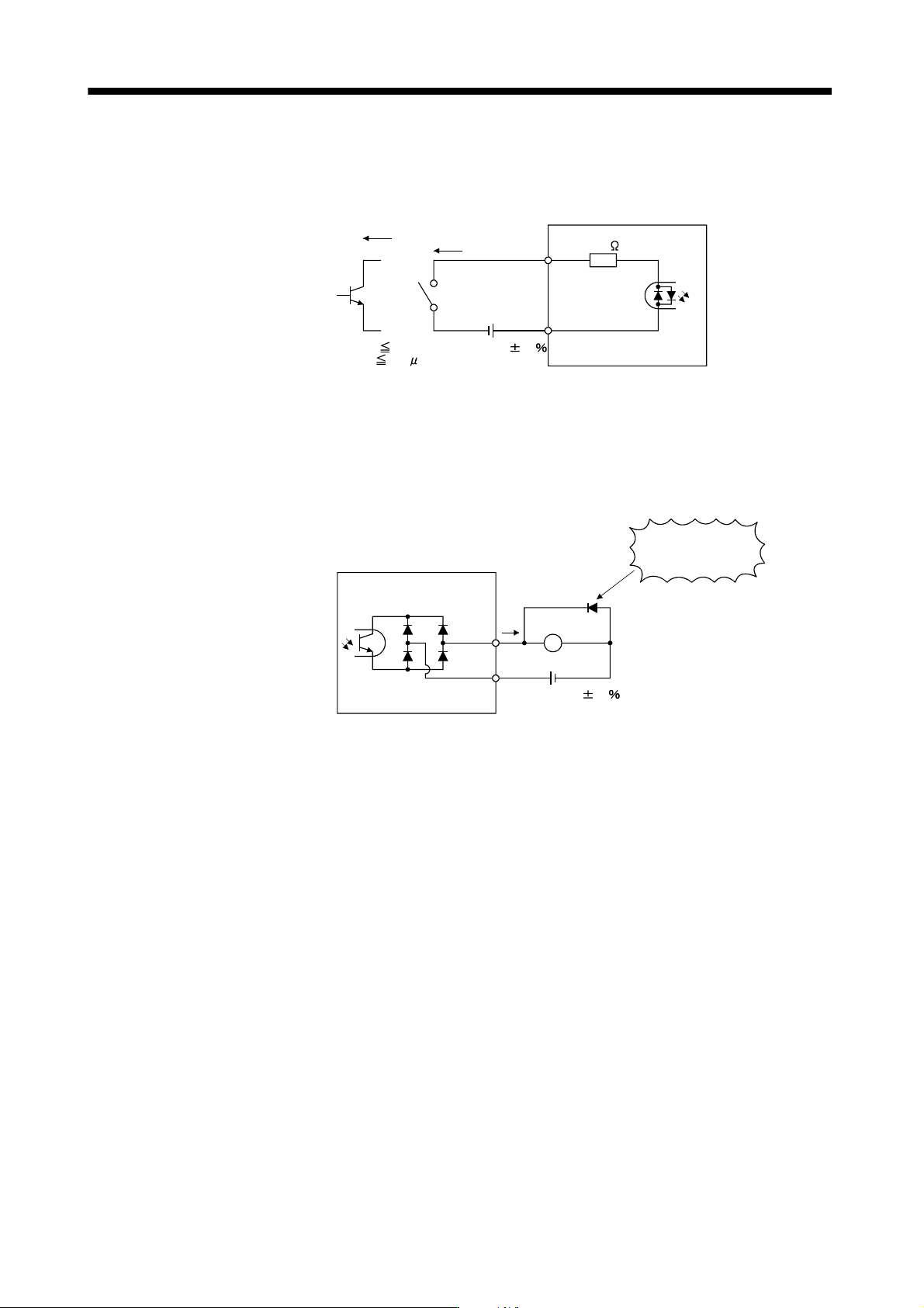
(2) I/O interfaces
(a) Digital input interface (DI)
Give a signal with a relay or open collector transistor. Refer to section 3.7.3 for the source input.
EM1
Converter unit
Switch
Approx. 5mA
For transistor
DICOM
V
CES
1.0V
I
CEO
100 A
TR
24VDC 10
150mA
5.6k
(b) Digital output interface (DO)
A lamp, relay or photocoupler can be driven. Install a diode for an inductive load, or install an inrush
current suppressing resistor for a lamp load. (Permissible current: 40mA or less, inrush current: 100mA
or less) A maximum of 2.6V voltage drop occurs in the servo amplifier.
Refer to section 3.7.3 for the source output.
Converter unit
ALM,
etc.
Load
DOCOM
24VDC 10
150mA
If polarity of diode is
reversed, converter
unit will fail.
(Note)
Note. If the voltage drop (maximum of 2.6V) interferes with the relay operation, apply high
voltage (up to 26.4V) from external source.
13 - 37
13. SERVO AMPLIFIERS WITH A LARGE CAPACITY
(
30k TO 55kW
)
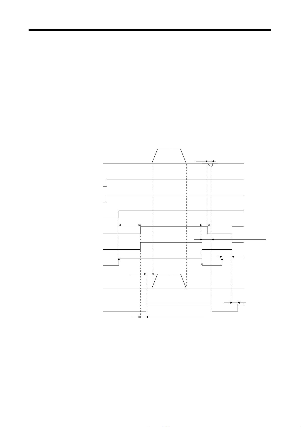
13.3.7 Timing chart
(1) Power circuit timing chart
Power-on procedure
(a) Always wire the power supply as shown in above section 13.3.2 using the magnetic contactor with the
main circuit power supply (3-phase: L
1
, L
2
, L
3
). Configure up an external sequence to switch off the
magnetic contactor as soon as an alarm occurs.
(b) Switch on the control circuit power supply L
11
, L
21
simultaneously with the main circuit power supply or
before switching on the main circuit power supply. If the main circuit power supply is not on, the display
shows the corresponding warning. However, by switching on the main circuit power supply, the warning
disappears and the drive unit will operate properly.
1) When control function of magnetic contactor is enabled and the status remains at ready on
The main circuit power is not shut off with servo off.
ON
OFF
Main circuit
power supply
ON
OFF
Servo on command
(from controller)
ON
OFF
Base circuit
ON
OFF
Converter unit control
power supply
ON
OFF
Drive unit control
power supply
(Note 1)
Electromagnetic
brake interlock (MBR)
0r/min
Servo motor speed
0r/min
Position command
(Note 4)
Release
Activate
Electromagnetic
brake
(95ms)
(3s)
(Note 5)
Tb
Coasting
Electromagnetic
brake operation
delay time
(Note 3)
Release delay time and external relay (Note 2)
ON
OFF
Release delay
time and external
relay (Note 2)
Note 1. ON: Electromagnetic brake is not activated.
OFF: Electromagnetic brake is activated
2. Electromagnetic brake is released after delaying for the release time of electromagnetic brake and operation time of
external circuit relay. For the release delay time of electromagnetic brake, refer to the Servo Motor Instruction Manual
(Vol.2).
3. Make the controller execute the position command after the electromagnetic brake is released.
4. In position control mode
5. “Tb” refers to a delay time when the electromagnetic brake interlock (MBR) is turned off until when the base circuit is shut
off at servo-off. Set Tb using parameter No.PC02.
13 - 38
13. SERVO AMPLIFIERS WITH A LARGE CAPACITY
(
30k TO 55kW
)
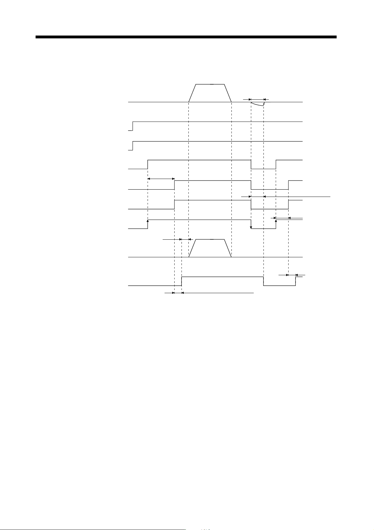
2) When control function of magnetic contactor is enabled and the status returns to ready off
The magnetic contactor of the converter unit is turned off with servo off, and the main circuit magnetic
contactor is shut off.
(3s)
(3s)
(Note 3)
ON
OFF
Main circuit
power supply
ON
OFF
Servo on command
(from controller)
ON
OFF
Base circuit
ON
OFF
Converter unit control
power supply
ON
OFF
Drive unit control
power supply
(Note 1)
Electromagnetic
brake interlock (MBR)
0r/min
Servo motor speed
0r/min
Position command
(Note 4)
Release
Activate
Electromagnetic
brake
Coasting
Electromagnetic
brake operation
delay time
ON
OFF
Release delay
time and external
relay (Note 2)
Release delay time and external relay (Note 2)
Note 1. ON: Electromagnetic brake is not activated.
OFF: Electromagnetic brake is activated
2. Electromagnetic brake is released after delaying for the release time of electromagnetic brake and operation time of
external circuit relay. For the release delay time of electromagnetic brake, refer to the Servo Motor Instruction Manual
(Vol.2).
3. Make the controller execute the position command after the electromagnetic brake is released.
4. In position control mode