sh030051g.pdf - 第39页
1 - 18 1. FUNCTIONS AND CONFIGURATIO N 1.7.2 Removal and reinstallation of the front cover WARNING Before removing or installing the front cover, turn off the power and wait for 15 minutes or more until the charge lamp t…
1 - 17
1. FUNCTIONS AND CONFIGURATION
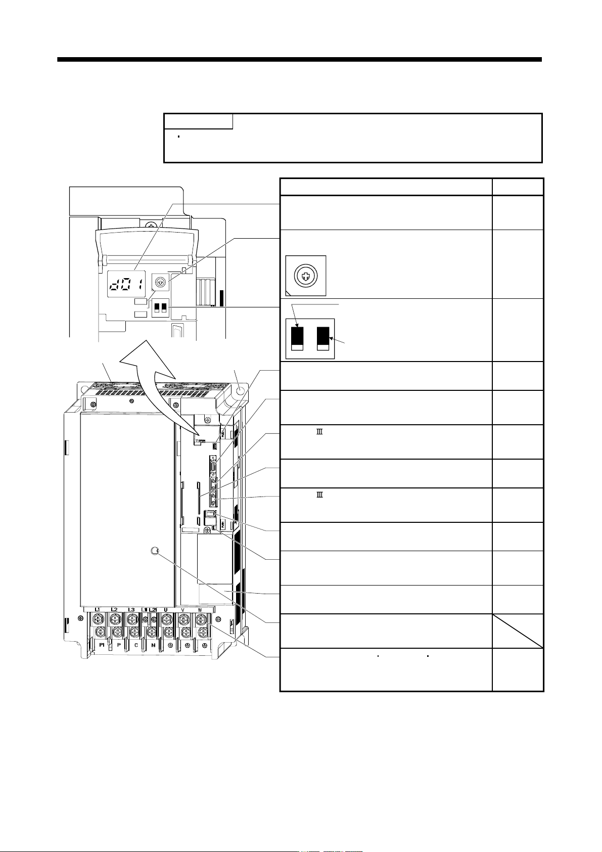
(7) MR-J3-11KB(4) to MR-J3-22KB(4)
POINT
The servo amplifier is shown without the front cover. For removal of the front
cover, refer to section 1.7.2.
7
9
6
8
5
4
3
2
1
0
F
E
D
C
B
A
12
ON 4F
SW1
SW2
TEST
Cooling fan
Fixed part
(4 places)
Used to set the axis No. of servo amplifier.
Rotary axis setting switch (SW1)
SW2
Test operation select switch (SW2-1)
Used to perform the test operation
mode by using MR Configurator.
Spare (Be sure to set to the "Down"
position).
Detailed
explanation
Section 3.13
Section 3.2
Section 3.4
SW1
Section 3.13
Name/Application
12
Display
The 3-digit, seven-segment LED shows the servo
status and alarm number.
USB communication connector (CN5)
Connect the personal computer.
I/O signal connector (CN3)
Used to connect digital I/O signals.
More over an analog monitor is output.
SSCNET cable connector (CN1A)
Used to connect the servo system controller or the front
axis servo amplifier.
SSCNET cable connector (CN1B)
Used to connect the rear axis servo amplifier. For the final
axis, puts a cap.
Encoder connector (CN2)
Used to connect the servo motor encoder.
Charge lamp
Lit to indicate that the main circuit is charged. While
this lamp is lit, do not reconnect the cables.
Battery connector (CN4)
Used to connect the battery for absolute position data
backup.
7
6
5
4
3
2
1
0
F
E
D
C
B
A
9
8
Chapter 4
Section 11.8
Section 3.2
Section 3.4
Section 3.2
Section 3.4
Section 3.4
Section 11.1
Section 11.9
Chapter 12
Rating plate
Section 1.5
Section 3.1
Section 3.3
Battery holder
Contains the battery for absolute position data backup.
Section 12.3
Main circuit terminal block control circuit protective
earth (TE)
Used to connect the input power supply, servo motor,
regenerative option and ground.
1 - 18
1. FUNCTIONS AND CONFIGURATION
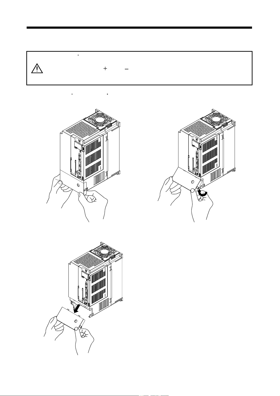
1.7.2 Removal and reinstallation of the front cover
WARNING
Before removing or installing the front cover, turn off the power and wait for 15
minutes or more until the charge lamp turns off. Then, confirm that the voltage
between P(
) and N( ) is safe with a voltage tester and others. Otherwise, an
electric shock may occur. In addition, always confirm from the front of the servo
amplifier whether the charge lamp is off or not.
(1) For MR-J3-350B4
MR-J3-500B(4) MR-J3-700B(4)
Removal of the front cover
A)
A)
Hold the ends of lower side of the front cover with
both hands.
Pull up the cover, supporting at point
A)
.
Pull out the front cover to remove.
1 - 19
1. FUNCTIONS AND CONFIGURATION
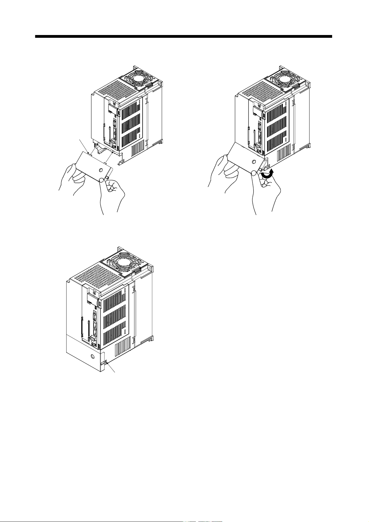
Reinstallation of the front cover
Front cover
setting tab
A)
A)
Insert the front cover setting tabs into the sockets of
servo amplifier (2 places).
Pull up the cover, supporting at point
A)
.
Setting tab
Push the setting tabs until they click.