sh030051g.pdf - 第321页
13 - 20 13. SERVO AMPLIFIERS WI TH A LARGE CAPACITY ( 30k TO 55kW ) 13.2 Installation CAUTION Stacking in excess of the limited num ber of products is not allowed. Install the equipment to incombustibles. Installing them…
13 - 19
13. SERVO AMPLIFIERS WITH A LARGE CAPACITY
(
30k TO 55kW
)
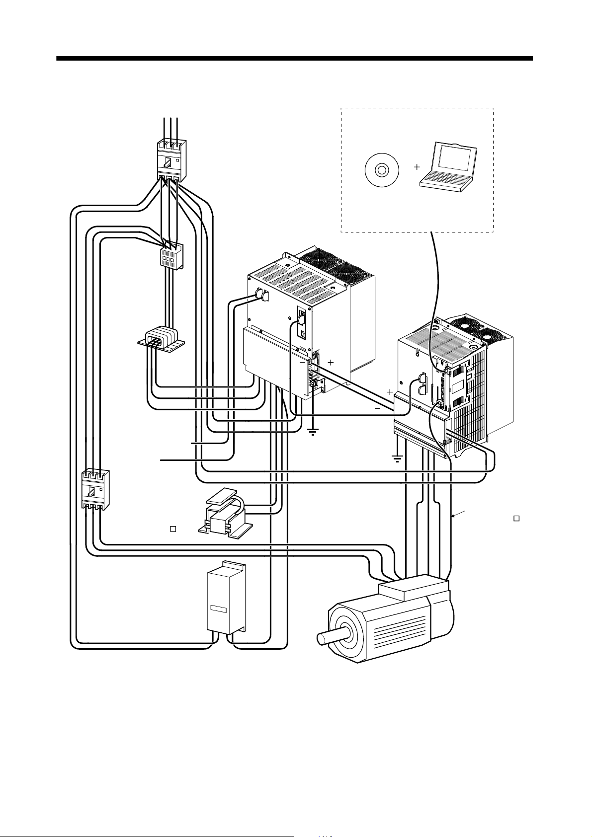
13.1.8 Servo system with auxiliary equipment
L
L
BV
BW
BU
L
11
L
21
L11
RS T
3-phase AC
power supply
MR Configurator
L
(Note 1)
Communication
cable
Drive unit(Note 3)
Converter unit
(MR-J3CDL05M)
Servo motor
HA-LP series
(Note 2)
VUEW
P2
P
1
L
1
L
2
L
3
P
C
S
R
L21
L
Magnetic contactor
operation coil
(I/O signal)
Encoder cable
(MR-HSCBL M)
Power factor improving
DC reactor
(MR-DCL K)
P
1
P
2
L
21
L11
Magnetic
contactor(MC)
No-fuse
breaker(NFB)
Line noise
filter(FR-BLF)
No-fuse
breaker(NFB)
Regenerative option
The MR Configurator is required for
parameter setting.
Personal
computer
C
Note 1. The L+ and L- connection conductors used to connect a converter unit to a drive unit are standard accessories. The converter
unit is attached to the drive unit actually. (Refer to section 13.2.1.)
2. The power supply of the servo motor cooling fan differs depending on the capacity of a servo motor. Refer to section 13.3.6.
3. For MR-J3-DU30KB4 or MR-J3-DU37KB4.
13 - 20
13. SERVO AMPLIFIERS WITH A LARGE CAPACITY
(
30k TO 55kW
)
13.2 Installation
CAUTION
Stacking in excess of the limited number of products is not allowed.
Install the equipment to incombustibles. Installing them directly or close to
combustibles will led to a fire.
Install the equipment in a load-bearing place in accordance with this Instruction
Manual.
Do not get on or put heavy load on the equipment to prevent injury.
Use the equipment within the specified environmental condition range. (For the
environmental conditions, refer to section 13.1.3.)
Provide an adequate protection to prevent screws, metallic detritus and other
conductive matter or oil and other combustible matter from entering the converter
unit
drive unit.
Do not block the intake/exhaust ports of the converter unit drive unit. Otherwise,
a fault may occur.
Do not subject the converter unit drive unit to drop impact or shock loads as they
are precision equipment.
Do not install or operate a faulty converter unit drive unit.
When the product has been stored for an extended period of time, consult
Mitsubishi.
When treating the converter unit drive unit, be careful about the edged parts
such as the corners of the converter unit
drive unit.
POINT
Explanations on the following item are the same as those for servo amplifiers
with 22kW or less. Refer to the section below for details.
Keep out foreign materials Refer to section 2.2.
Cable stress Refer to section 2.3.
SSCNET cable laying Refer to section 2.4.
Parts Having Service Lives Refer to section 2.6.
13 - 21
13. SERVO AMPLIFIERS WITH A LARGE CAPACITY
(
30k TO 55kW
)
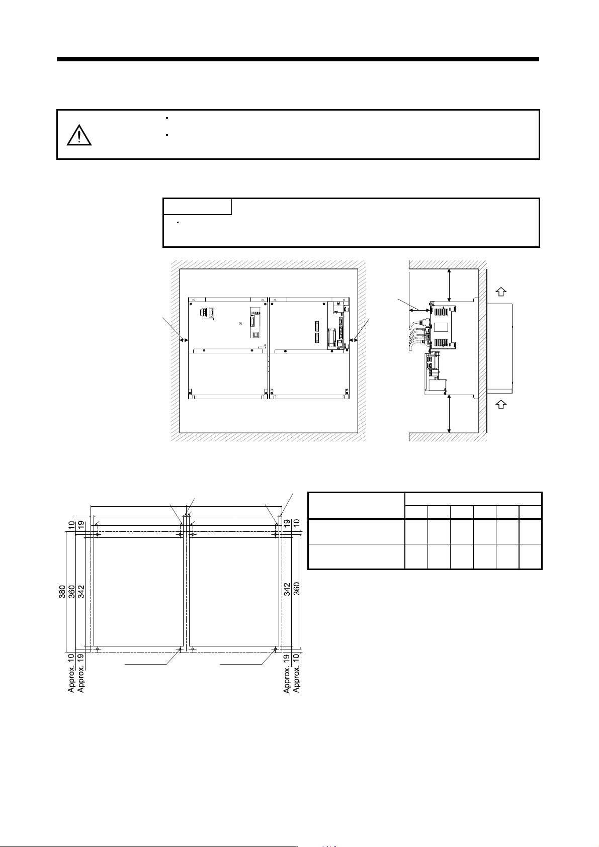
13.2.1 Installation direction and clearances
CAUTION
Install the equipment in the specified direction. Not doing so can cause a failure.
Leave the specified clearances between the converter unit/drive unit and the
control box inside walls or other equipment. Not doing so can cause a failure.
(1) Installation
POINT
Make sure to connect a drive unit to the right side of a converter unit as
shown in the diagram.
80mm or
more
Side view
Drive unitConverter unit
Front view
100mm or
more
120mm or more
30mm or
more
30mm or
more
Cooling fan
wind direction
Air
intake
(2) Mounting dimensional diagram
9.5
Converter unit
punched hole
Drive unit
punched hole
4-M6 screw
300
20
260
281
Approx. 9.5
Approx. 20
4-M6 screw
W1
W3
W2
W4
Approx. W5
Approx. W3
W5
[Unit: mm]
Drive unit model
Dimensions
W1 W2 W3 W4 W5 A
MR-J3-DU30KB, 37KB,
45KB4, 55KB4
300 260 20 281 9.5 M6
MR-J3-DU30KB4,
37KB4
240 120 60 222 9 M5
(3) Others
When using heat generating equipment such as the regenerative option, install them with full consideration
of heat generation so that the converter unit and drive unit is not affected.
Install the converter unit and drive unit on a perpendicular wall in the correct vertical direction.