sh030051g.pdf - 第157页
6 - 12 6. GENERAL GAIN ADJUSTMEN T 6.5 Differences between MELSERVO-J2-Supe r and MELSERVO-J3 in auto tuning To meet higher response demands, the MELSERVO-J3 series has been changed in response level setting range from t…
6 - 11
6. GENERAL GAIN ADJUSTMENT
6.4 Interpolation mode
The interpolation mode is used to match the position loop gains of the axes when performing the interpolation
operation of servo motors of two or more axes for an X-Y table or the like. In this mode, manually set the model
loop gain that determines command track ability. Other parameters for gain adjustment are set automatically.
(1) Parameter
(a) Automatically adjusted parameters
The following parameters are automatically adjusted by auto tuning.
Parameter No. Abbreviation Name
PB06 GD2 Ratio of load inertia moment to servo motor inertia moment
PB08 PG2 Position loop gain
PB09 VG2 Speed loop gain
PB10 VIC Speed integral compensation
(b) Manually adjusted parameters
The following parameters are adjustable manually.
Parameter No. Abbreviation Name
PB07 PG1 Model loop gain
(2) Adjustment procedure
Step Operation Description
1 Set to the auto tuning mode. Select the auto tuning mode 1.
2
During operation, increase the response level setting (parameter
No.PA09), and return the setting if vibration occurs.
Adjustment in auto tuning mode 1.
3 Check the values of model loop gain. Check the upper setting limits.
4 Set the interpolation mode (parameter No.PA08: 0000). Select the interpolation mode.
5
Set the model loop gain of all the axes to be interpolated to the same
value. At that time, adjust to the setting value of the axis, which has the
smallest model loop gain.
Set position loop gain.
6
Looking at the interpolation characteristic and rotation status, fine-adjust
the gains and response level setting.
Fine adjustment.
(3) Adjustment description
(a) Model loop gain (parameter No.PB07)
This parameter determines the response level of the position control loop. Increasing model loop gain
improves track ability to a position command but a too high value will make overshooting liable to occur
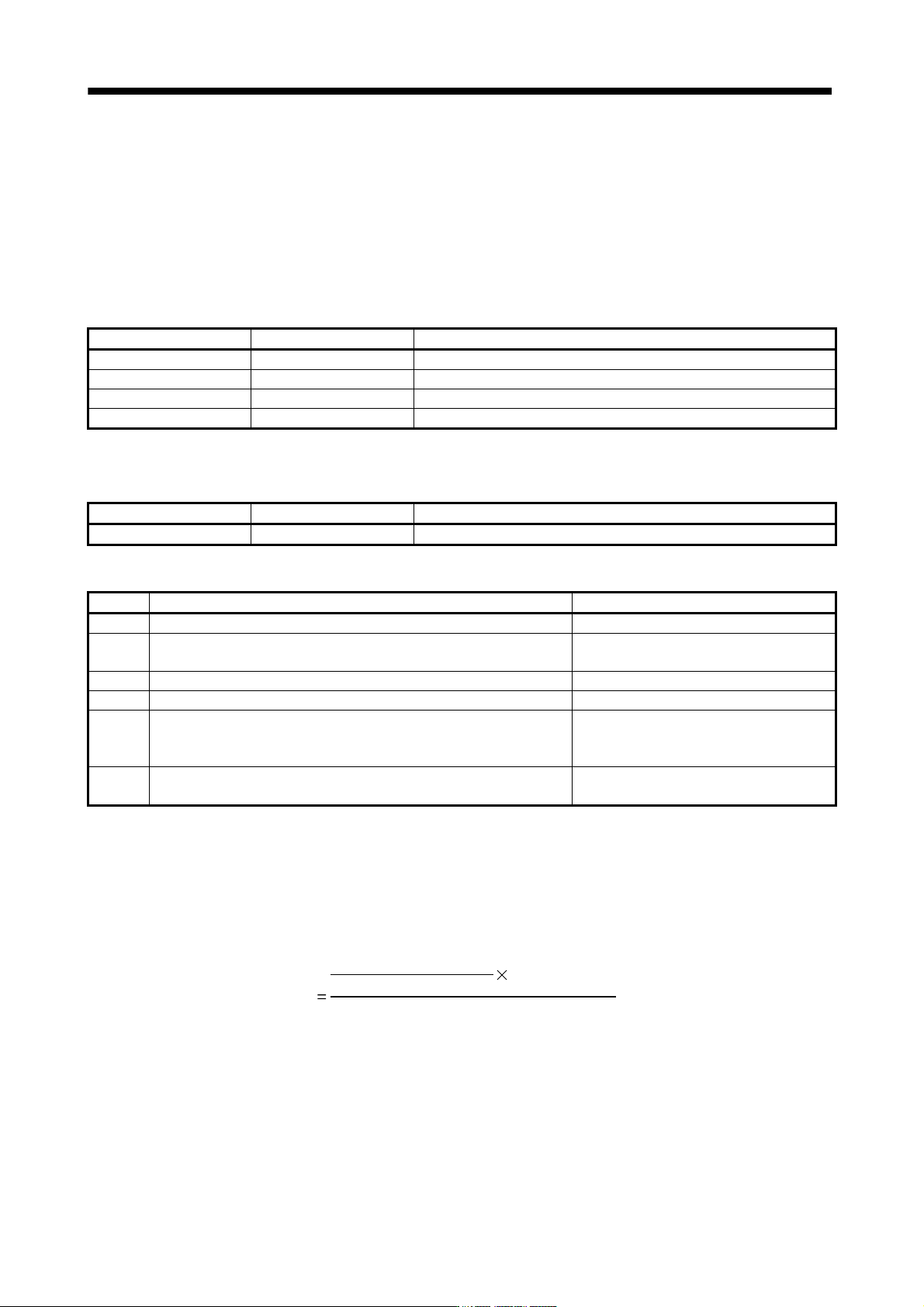
at the time of settling. The droop pulse value is determined by the following expression.
60
Rotation speed (r/min)
Model loop gain setting
Droop pulse value (pulse)
262144(pulse)
6 - 12
6. GENERAL GAIN ADJUSTMENT
6.5 Differences between MELSERVO-J2-Super and MELSERVO-J3 in auto tuning
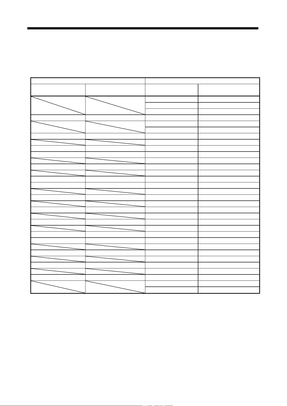
To meet higher response demands, the MELSERVO-J3 series has been changed in response level setting
range from the MELSERVO-J2S-Super series. The following table lists comparison of the response level
setting.
MELSERVO-J2-Super MELSERVO-J3
Parameter No.9 setting
Guideline for machine resonance
frequency [Hz]
Parameter No.PA09 setting
Guideline for machine resonance
frequency [Hz]
1 10.0
2 11.3
3 12.7
1 15 4 14.3
5 16.1
6 18.1
2 20 7 20.4
8 23.0
3 25 9 25.9
4 30 10 29.2
11 32.9
5 35 12 37.0
13 41.7
6 45 14 47.0
7 55 15 52.9
16 59.6
8 70 17 67.1
18 75.6
9 85 19 85.2
20 95.9
A 105 21 108.0
22 121.7
B 130 23 137.1
C 160 24 154.4
25 173.9
D 200 26 195.9
27 220.6
E 240 28 248.5
29 279.9
F 300 30 315.3
31 355.1
32 400.0
Note that because of a slight difference in gain adjustment pattern, response may not be the same if the
resonance frequency is set to the same value.
7 - 1
7. SPECIAL ADJUSTMENT FUNCTIONS
7. SPECIAL ADJUSTMENT FUNCTIONS
POINT
The functions given in this chapter need not be used generally. Use them if
you are not satisfied with the machine status after making adjustment in the
methods in chapter 7.
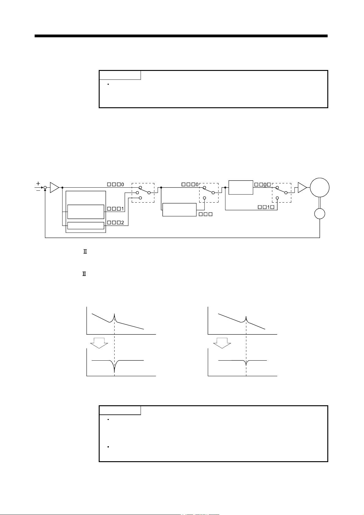
If a mechanical system has a natural resonance point, increasing the servo system response level may cause
the mechanical system to produce resonance (vibration or unusual noise) at that resonance frequency.
Using the machine resonance suppression filter and adaptive tuning can suppress the resonance of the
mechanical system.
7.1 Function block diagram
Parameter
No.PB23
Parameter
No.PB16
Parameter
No.PB01
Adaptive tuning
Manual setting
Speed
control
Machine resonance
suppression filter 2
Encoder
Current
command
Low-pass
filter
Servo
motor
Machine resonance
suppression filter
1
7.2 Adaptive filter
(1) Function
Adaptive filter
(adaptive tuning) is a function in which the servo amplifier detects machine vibration for a
predetermined period of time and sets the filter characteristics automatically to suppress mechanical system
vibration. Since the filter characteristics (frequency, depth) are set automatically, you need not be conscious
of the resonance frequency of a mechanical system.
Mechanical
system
response
level
Mechanical
system
response
level
Machine resonance point
Machine resonance point
Frequency Frequency
Notch
depth
Notch
depth
Notch frequency Notch frequency
Frequency Frequency
When machine resonance is large and frequency is low When machine resonance is small and frequency is high
POINT
The machine resonance frequency which adaptive tuning mode can respond
to is about 100 to 2.25kHz. Adaptive vibration suppression control has no
effect on the resonance frequency outside this range.
Adaptive vibration suppression control may provide no effect on a mechanical
system which has complex resonance characteristics.