sh030051g.pdf - 第231页
11 - 26 11. OPTIONS AND AUXILI ARY EQUIPMENT (b) MR-J3-350B4 MR-J3-500B(4) MR-J3-700B(4) Always remove the wiring (across P-C) of the servo amplifier bu ilt-in regenerative resistor and fit the regenerative option across…
11 - 25
11. OPTIONS AND AUXILIARY EQUIPMENT
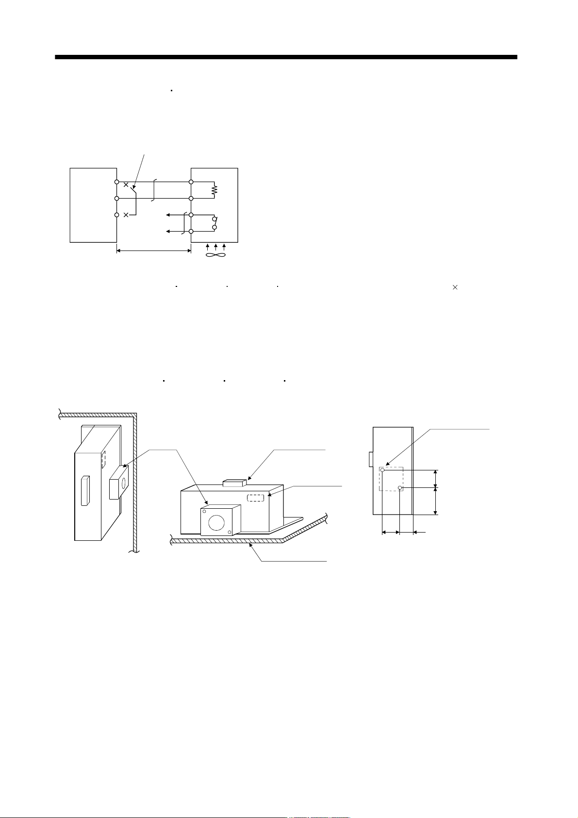
(a) MR-J3-350B or less
MR-J3-200B4 or less
Always remove the wiring from across P-D and fit the regenerative option across P-C.
The G3 and G4 terminals act as a thermal sensor. G3-G4 is disconnected when the regenerative option
overheats abnormally.
D
P
C
G4
G3
C
P
Regenerative option
5m max.
Servo amplifier
Always remove the lead from across P-D.
(Note 2)
Cooling fan
(Note 1)
Note 1. When using the MR-RB50 MR-RB3M-4 MR-RB3G-4 MR-RB5G-4, forcibly cool it with a cooling fan (92 92, minimum air
flow : 1.0m
3
).
2. Make up a sequence which will switch off the magnetic contactor (MC) when abnormal heating occurs.
G3-G4 contact specifications
Maximum voltage: 120V AC/DC
Maximum current: 0.5A/4.8VDC
Maximum capacity: 2.4VA
For the MR-RB50
MR-RB3M-4 MR-RB3G-4 MR-RB5G-4 install the cooling fan as shown.
(for cooling fan installation)
Depth 10 or less
(Screw hole already
machined)
Cooling fan installation screw hole dimensions
82.5
40
82.5
133
2-M3 screw hole
Terminal block
Thermal relay
Installation surface
Horizontal installation
Vertical
installation
Top
Bottom
[Unit : mm]
Cooling fan
11 - 26
11. OPTIONS AND AUXILIARY EQUIPMENT
(b) MR-J3-350B4
MR-J3-500B(4) MR-J3-700B(4)
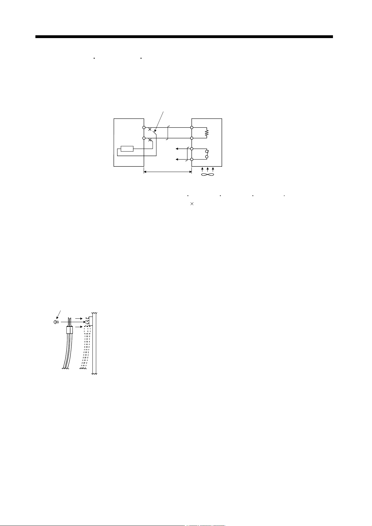
Always remove the wiring (across P-C) of the servo amplifier built-in regenerative resistor and fit the
regenerative option across P-C.
The G3 and G4 terminals act as a thermal sensor. G3-G4 is opened when the regenerative option
overheats abnormally.
Regenerative optionServo amplifier
Cooling fan(Note 1)
P
C
G4
G3
C
P
Always remove wiring (across P-C) of servo
amplifier built-in regenerative resistor.
5m or less
(Note 2)
Note 1. When using the MR-RB51 MR-RB3G-4 MR-RB5G-4 MR-RB34-4 MR-RB54-4, forcibly
cool it with a cooling fan (92
92, minimum air flow : 1.0m
3
).
2. Make up a sequence which will switch off the magnetic contactor (MC) when abnormal heating
occurs.
G3-G4 contact specifications
Maximum voltage: 120V AC/DC
Maximum current: 0.5A/4.8VDC
Maximum capacity: 2.4VA
When using the regenerative resistor option, remove the servo amplifier's built-in regenerative resistor
terminals (across P-C), fit them back to back, and secure them to the frame with the accessory screw as
shown below.
Mounting method
Accessory screw
11 - 27
11. OPTIONS AND AUXILIARY EQUIPMENT
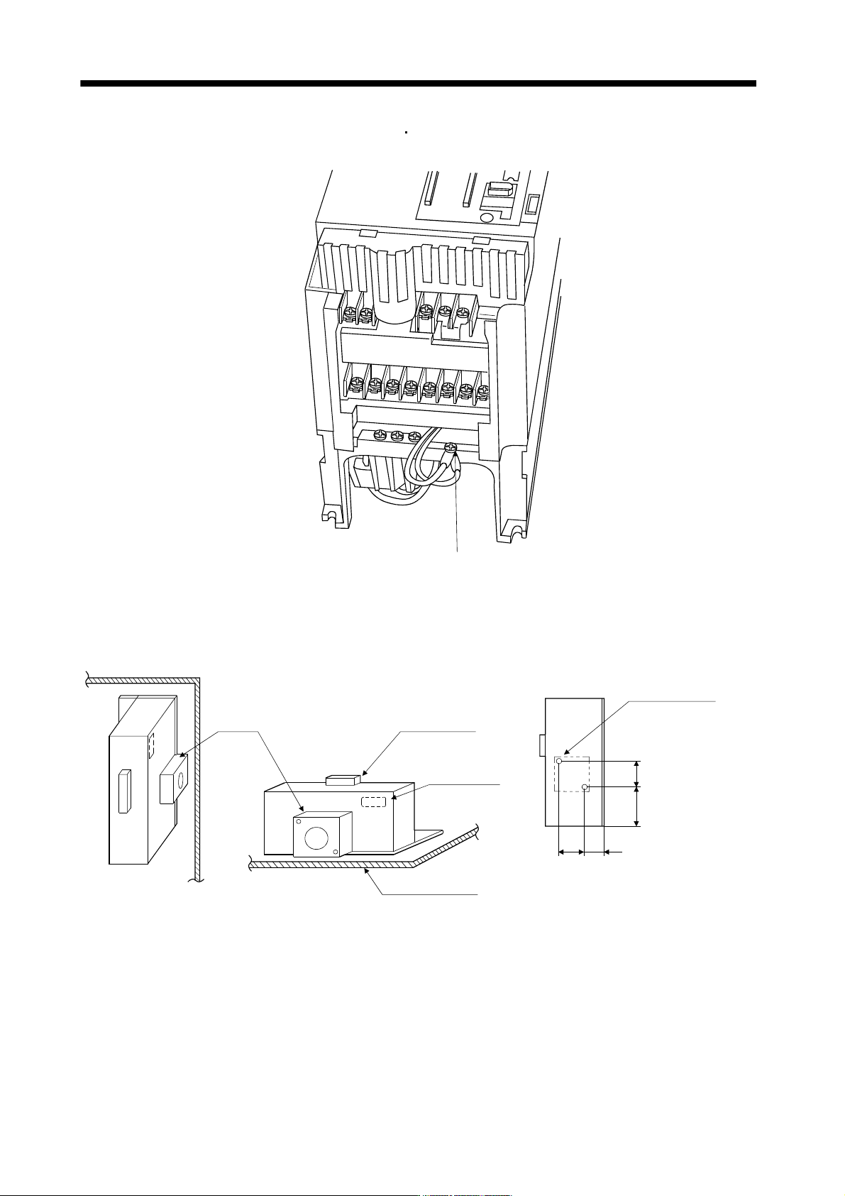
The drawing below shows the MR-J3-350B4
MR-J3-500B(4). Refer to section 9.1 (6) outline drawings
for the position of the fixing screw for MR-J3-700B(4).
Built-in regenerative resistor
lead terminal fixing screw
For the MR-RB51, MR-RB3G-4, MR-RB5G-4, MR-RB34-4 or MR-RB54-4 install the cooling fan as
shown.
(for cooling fan installation)
Depth 10 or less
(Screw hole already
machined)
Cooling fan installation screw hole dimensions
82.5
40
82.5
133
2-M3 screw hole
Terminal block
Thermal relay
Installation surface
Horizontal installation
Vertical
installation
Top
Bottom
[Unit : mm]
Cooling fan