sh030051g.pdf - 第351页
13 - 50 13. SERVO AMPLIFIERS WI TH A LARGE CAPACITY ( 30k TO 55kW ) 13.4.2 Status display mode The servo status during operation is sho wn on the 3-digit, 7-segme nt LED display. Press the "UP" or "DOW N&q…
13 - 49
13. SERVO AMPLIFIERS WITH A LARGE CAPACITY
(
30k TO 55kW
)
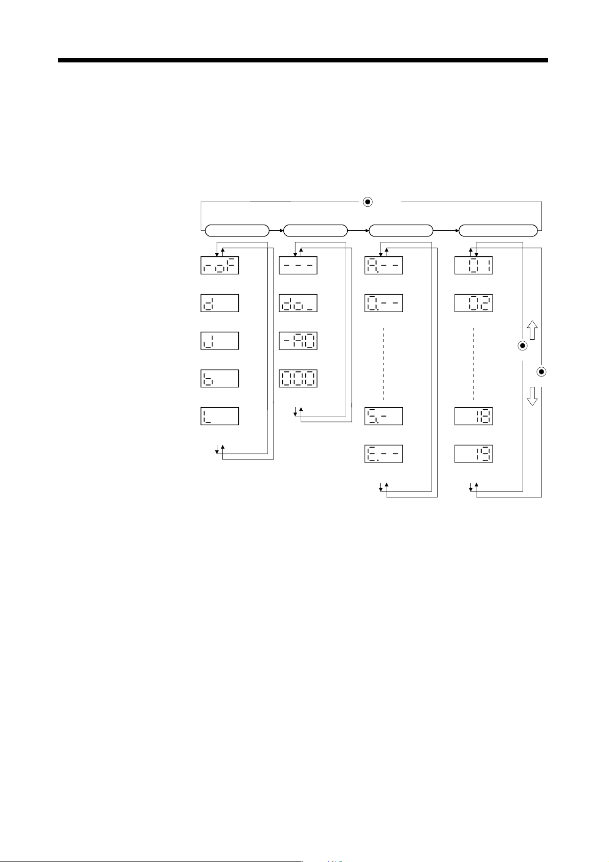
13.4 Display section and operation section of the converter unit
13.4.1 Display flowchart
Use the display (3-dight, 7-segment LED) on the front panel of the converter unit for status display, parameter
setting, etc. Set the parameters before operation, diagnose an alarm, confirm external sequences, and/or
confirm the operation status.
Press the MODE, UP or DOWN button once to move the next screen.
Current alarm
Sixth alarm in
past
Status display
UP
MODE
Button
Alarm Basic parameters
Effective load
ratio [%]
Peak load ratio
[%]
Bus voltage
[V]
First alarm in
past
Parameter
No.PA02
Parameter
No.PA01
Parameter error
No.
Parameter
No.PA19
Parameter
No.PA18
External I/O
signal display
Output signal
forced output
Diagnosis
Software version
high
Software version
low
Regenerative load
ratio [%]
Status
(Note)
(Note)
(Note)
(Note)
DOWN
Note. When parameter is selected, parameter group and parameter No. are displayed
alternately. Refer to section 13.4.5 for details.
13 - 50
13. SERVO AMPLIFIERS WITH A LARGE CAPACITY
(
30k TO 55kW
)
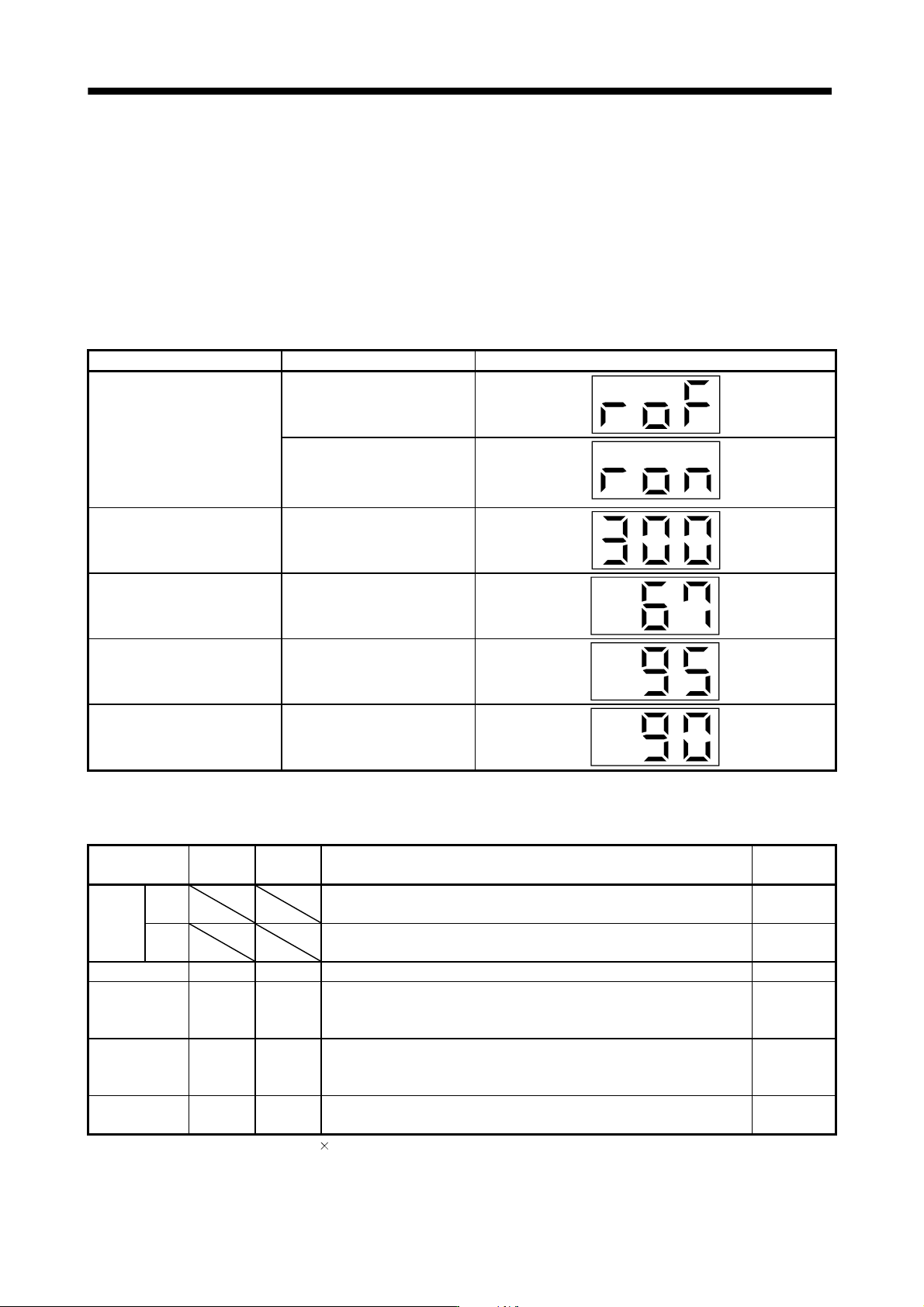
13.4.2 Status display mode
The servo status during operation is shown on the 3-digit, 7-segment LED display. Press the "UP" or "DOWN"
button to change display data as desired.
When the required data is selected, the corresponding symbol is displayed. Press the "SET" button to display
that data.
The converter unit display section can show four items of data such as the effective load factor.
(1) Display examples
The following table shows the display examples.
Item Status Display
Status
Ready off
Ready on
Bus voltage 300[V]
Effective load ratio 67[%]
Peak load ratio 95[%]
Regenerative load ratio 90[%]
(2) Status display list
The following table lists the converter unit statuses that may be displayed.
Status display Symbol Unit Description
Indication
range
Status
Ready
off
The ready off is displayed during initialization or alarm occurrence, in the
forced stop status, or when the bus voltage is not established.
roF
Ready
on
The ready on is displayed when the servo was switched on after completion
of initialization and the servo amplifier is ready to operate.
ron
Bus voltage d V The converter unit voltage is displayed. 0 to 999
Effective load
ratio
J %
Continuous effective load torque is displayed. (Note)
The effective value in the past 15 seconds is displayed relative to the rated
current of 100%.
0 to 300
Peak load ratio b %
The peak output is displayed. (Note)
The peak value in the past 15 seconds is displayed relative to the rated
torque of 100%.
0 to 400
Regenerative
load ratio
L %
The percentage of regenerative power to the permissible regenerative value
is displayed.
0 to 300
Note. Output = converter unit bus voltage output current
13 - 51
13. SERVO AMPLIFIERS WITH A LARGE CAPACITY
(
30k TO 55kW
)
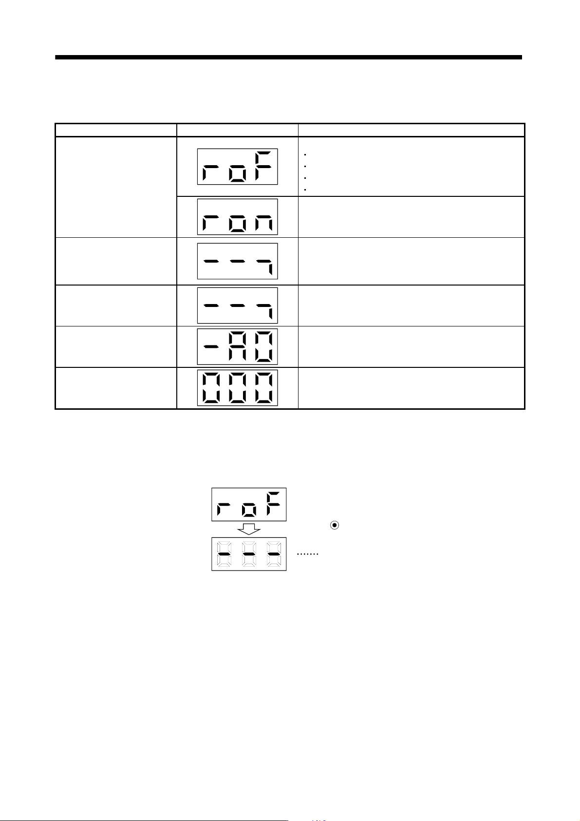
13.4.3 Diagnostic mode
(1) Diagnostic list
Name Display Unit
Sequence
Not ready.
Initializing.
An alarm occurred.
External forced stop status.
Bus voltage is not established.
Ready
Indicates that the servo was switched on after completion of
initialization and the drive unit is ready to operate.
External I/O signal display
Indicates the ON/OFF status of external I/O signal.
Lit : ON
Extinguished: OFF
For details, refer to (2) of this section.
Output signal forced output
Allows external I/O signal to be switched on/off forcibly. For
details, refer to (3) of this section.
Software version low
Indicates the version of the software.
Software version high
Indicates the system number of the software.
(2) External I/O signal display
The ON/OFF states of the digital I/O signals connected to the converter unit can be confirmed.
(a) Operation
Call the display screen shown after power-on. Using the "MODE" button, show the diagnostic screen.
External I/O signal display screen
Press MODE once.