sh030051g.pdf - 第255页
11 - 50 11. OPTIONS AND AUXILI ARY EQUIPMENT (3) Connection diagram (a) 200V class P 1 DOCOM RA1 EM1 C B R/L 11 3-phase 200 to 230VAC S/L 21 T/L 31 R2/L 1 S2/L 22 R2/L 12 T2/L 32 S2/L 2 (Note 3) P24 SD RDYB RDYA RSO SE A…
11 - 49
11. OPTIONS AND AUXILIARY EQUIPMENT
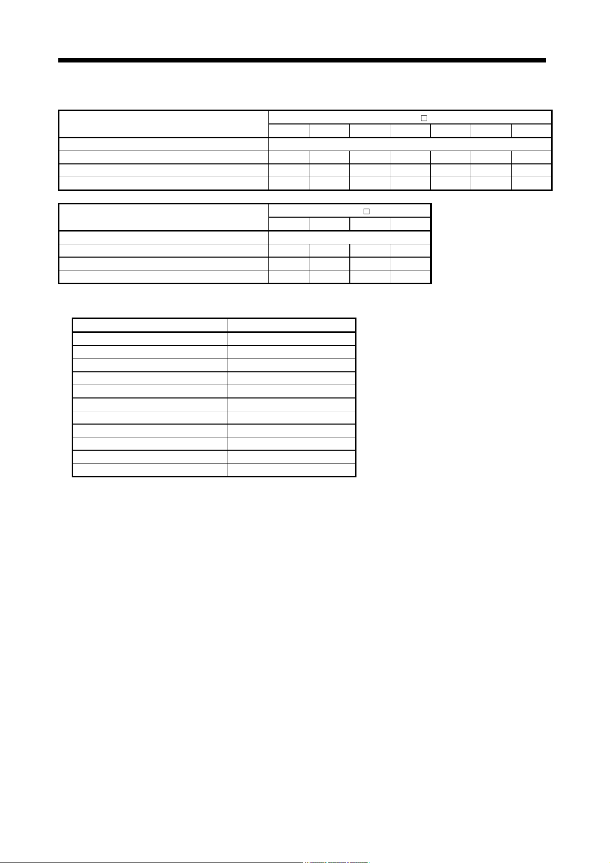
The following table lists the restrictions.
Item
FR-CV-
7.5K 11K 15K 22K 30K 37K 55K
Maximum number of connected servo amplifiers 6
Total of connectable servo amplifier capacities [kW] 3.75 5.5 7.5 11 15 18.5 27.5
Total of connectable servo motor rated currents [A] 33 46 61 90 115 145 215
Maximum servo amplifier capacity [kW] 3.5 5 7 11 15 15 22
Item
FR-CV-H
22K 30K 37K 55K
Maximum number of connected servo amplifiers 6
Total of connectable servo amplifier capacities [kW] 11 15 18.5 27.5
Total of connectable servo motor rated currents [A] 90 115 145 215
Maximum servo amplifier capacity [kW] 11 15 15 22
When using the FR-CV-(H), always install the dedicated stand-alone reactor (FR-CVL-(H)).
Power regeneration common converter Dedicated stand-alone reactor
FR-CV-7.5K(-AT) FR-CVL-7.5K
FR-CV-11 K(-AT) FR-CVL-11 K
FR-CV-15K(-AT) FR-CVL-15K
FR-CV-22K(-AT) FR-CVL-22K
FR-CV-30K(-AT) FR-CVL-30K
FR-CV-37K FR-CVL-37K
FR-CV-55K FR-CVL-55K
FR-CV-H22K(-AT) FR-CVL-H22K
FR-CV-H30K(-AT) FR-CVL-H30K
FR-CV-H37K FR-CVL-H37K
FR-CV-H55K FR-CVL-H55K
11 - 50
11. OPTIONS AND AUXILIARY EQUIPMENT
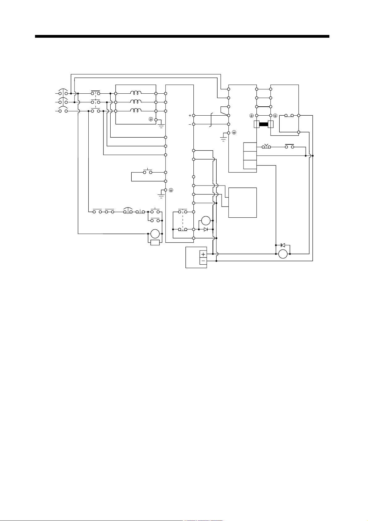
(3) Connection diagram
(a) 200V class
P
1
DOCOM
RA1
EM1
C
B
R/L11
3-phase
200 to
230VAC
S/L
21
T/L
31
R2/L1
S2/L
22
R2/L12
T2/L
32
S2/L2
(Note 3)
P24
SD
RDYB
RDYA
RSO
SE
A
T2/L
3
R/L
11
S/L
21
T/MC1
RES
SD
(Note 1)
L
11
L
21
P
N
U
V
W
(Note 1)
EM1
(Note 2)
RA1
RA2
24VDC
power
supply
Thermal
relay
OHS2
OHS1
CN2
MC
NF
FR-CVL FR-CV
MC
RA1 RA2
EM1
OFF
ON
RESET
SK
MC
(Note 1)
Servo motorServo amplifier
(Note 4)
Servo system
controller
(Note 5)
(Note 1)
(Note 7)
DICOM
N/L
P/L
U
V
W
(Note 6)
Note 1. Configure a sequence that will shut off main circuit power at an emergency stop or at FR-CV or servo amplifier alarm
occurrence.
2. For the servo motor with thermal relay, configure a sequence that will shut off main circuit power when the thermal relay
operates.
3. For the servo amplifier, configure a sequence that will switch the servo on after the FR-CV is ready.
4. For the FR-CV, the RSO signal turns off when it is put in a ready-to-operate status where the reset signal is input.
Configure a sequence that will make the servo inoperative when the RSO signal is on.
5. Configure a sequence that will make a stop with the emergency stop input of the servo system controller if an alarm occurs in
the FR-CV. When the servo system controller does not have an emergency stop input, use the forced stop input of the servo
amplifier to make a stop as shown in the diagram.
6. When using the servo amplifier of 7kW or less, make sure to disconnect the wiring of built-in regenerative resistor (3.5kW or
less: P and D, 5k/7kW: P and C).
7. When using the servo amplifier of 11k to 22kW, make sure to connect P
1 and P. (Factory-wired.)
11 - 51
11. OPTIONS AND AUXILIARY EQUIPMENT
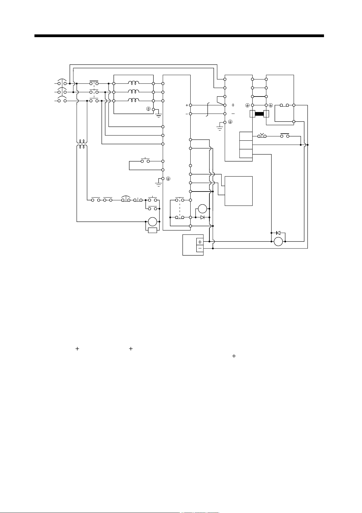
(b) 400V class
P
1
(Note 8)
Stepdown
transformer
DOCOM
RA1
EM1
C
B
R/L11
3-phase
380 to
480VAC
S/L
21
T/L
31
R2/L1
S2/L
22
R2/L12
T2/L
32
S2/L2
(Note 3)
P24
SD
RDYB
RDYA
RSO
SE
A
T2/L
3
R/L
11
S/L
21
T/MC1
RES
SD
(Note 1)
L
11
L
21
P( )
N( )
U
V
W
(Note 1)
EM1
(Note 2)
RA1
RA2
24VDC
power
supply
Thermal
relay
OHS2
OHS1
CN2
MC
NF
FR-CVL FR-CV-H
MC
RA1 RA2
EM1
OFF
ON
RESET
SK
MC
(Note 1)
Servo motorServo amplifier
(Note 4)
Servo system
controller
(Note 5)
(Note 1)
(Note 7)
DICOM
N/L
P/L
U
V
W
(Note 6)
Note 1. Configure a sequence that will shut off main circuit power at an emergency stop or at FR-CV-H or servo amplifier alarm
occurrence.
2. For the servo motor with thermal relay, configure a sequence that will shut off main circuit power when the thermal relay
operates.
3. For the servo amplifier, configure a sequence that will switch the servo on after the FR-CV-H is ready.
4. For the FR-CV-H, the RSO signal turns off when it is put in a ready-to-operate status where the reset signal is input.
Configure a sequence that will make the servo inoperative when the RSO signal is on.
5. Configure a sequence that will make a stop with the emergency stop input of the servo system controller if an alarm occurs
in the FR-CV-H. When the servo system controller does not have an emergency stop input, use the forced stop input of the
servo amplifier to make a stop as shown in the diagram.
6. When using the servo amplifier of 7kW or less, make sure to disconnect the wiring of built-in regenerative resistor (2kW or
less: P
and D, 3.5k to 7kW: P and C).
7. When using the servo amplifier of 11k to 22kW, make sure to connect P
1
and P( ). (Factory-wired.)
8. Stepdown transformer is required for coil voltage of magnetic contactor more than 200V class servo amplifiers.