sh030051g.pdf - 第326页
13 - 25 13. SERVO AMPLIFIERS WI TH A LARGE CAPACITY ( 30k TO 55kW ) (1) Enabling control function of m agnetic contactor (parameter No .PA02 1 (initial value)) Connecting the magnetic contactor control connector (CNP1) t…
13 - 24
13. SERVO AMPLIFIERS WITH A LARGE CAPACITY
(
30k TO 55kW
)
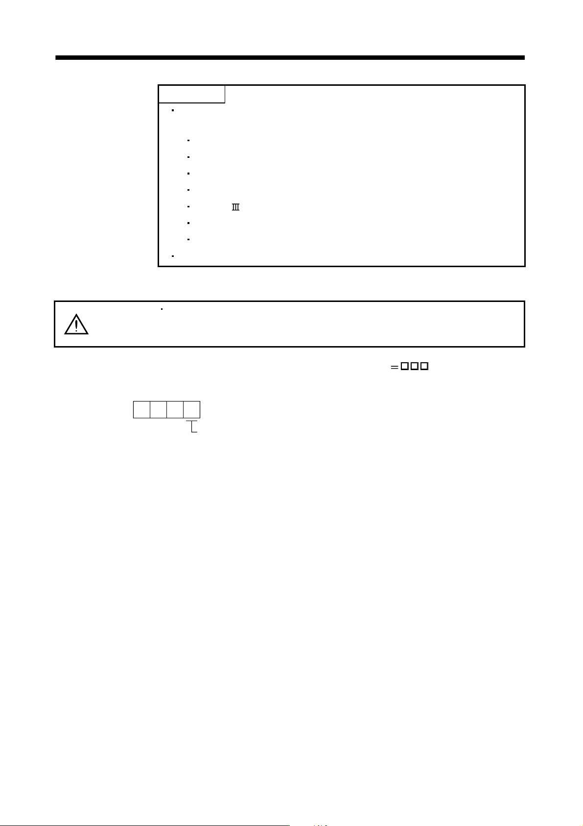
POINT
Explanations on the following item are the same as those for servo amplifiers
with 22kW or less. Refer to the section below for details.
I/O signal connection example Refer to section 3.2.
Signal (device) explanations Refer to section 3.5.
Interfaces Refer to section 3.7.
Treatment of cable shield external conductor Refer to section 3.8.
SSCNET cable connection Refer to section 3.9.
Grounding Refer to section 3.12.
Control axis selection Refer to section 3.13.
The pins with the same signal name are connected in the drive unit.
13.3.1 Magnetic contactor control connector (CNP1)
WARNING
Always connect the magnetic contactor wiring connector to the converter unit. If the
connector is not connected, an electric shock may occur since CNP1-1 and L
11 are
always conducting.
By enabling the control function of the magnetic contactor (parameter No.PA02
1 (initial value)), main
circuit power supply can be shut off automatically when an alarm occurs on the converter unit or the drive unit.
Used to select the output of the external magnet contactor drive signal.
0: No used
1: Used (initial value)
1
Parameter No.PA02
13 - 25
13. SERVO AMPLIFIERS WITH A LARGE CAPACITY
(
30k TO 55kW
)
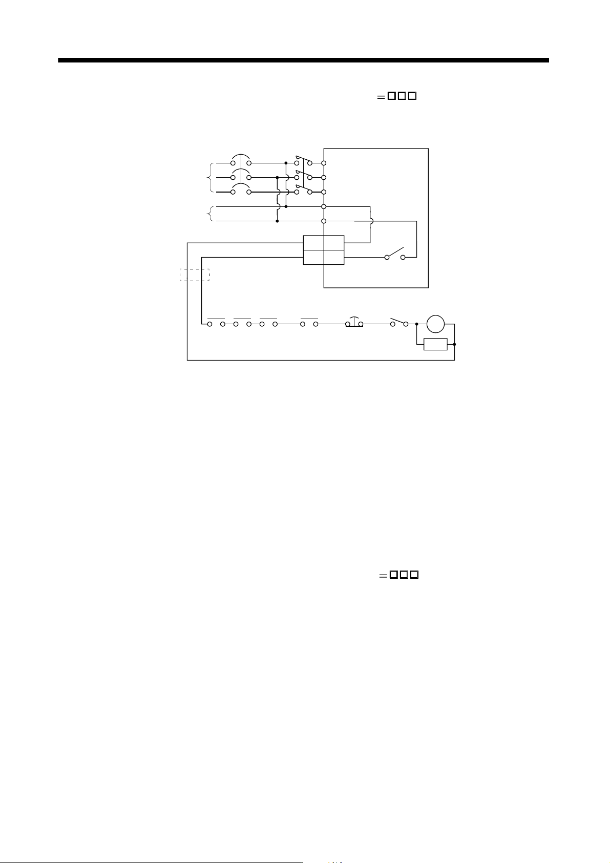
(1) Enabling control function of magnetic contactor (parameter No.PA02
1 (initial value))
Connecting the magnetic contactor control connector (CNP1) to the operating coil of the magnetic contactor
enables to control the magnetic contactor.
Converter unit
L
11
L
21
Power supply
MC
NFB
1MC1
2MC2
CNP1
Control circuit
power supply
RA3
RA1 RA2
EM1 OFF/ON
SK
Converter
unit trouble
Servo motor
thermal relay
Operation
-ready
Drive unit
trouble
RA4
Controller
forced stop
Forced stop
MC
L
1
L
2
L
3
(Note)
Note. Stepdown transformer is required when coil voltage of the magnetic contactor is 200V class, and the converter unit and the drive
unit are 400V class.
When the converter unit receives a start command from the drive unit while the magnetic contactor control
connector (CNP1) is connected to the magnetic contactor (refer to section 13.3.2 (1)), CNP1-2 and L
21
conduct in the converter unit. Then the control circuit power is supplied to turn ON the magnetic contactor
and the main circuit power is supplied to the converter unit.
Either when an alarm occurs on the converter unit or the drive unit while the control function of the magnetic
contactor is enabled, or when the forced stop (EM1) of the converter unit or the drive unit is turned OFF, the
switch between CNP1-2 and L
21 in the converter unit is disconnected and the main circuit power supply is
automatically shut off.
To automatically shut off the main circuit power supply by alarm, enable the control function of the magnetic
contactor.
(2) Disabling control function of magnetic contactor (parameter No.PA02
0)
When not connecting the magnetic contactor control connector (CNP1) to the operating coil of the magnetic
contactor, configure the circuit to shut off the main circuit power supply when detecting an alarm since the
main circuit power supply is not automatically shut off even when an alarm occurs on the converter unit or
the drive unit.
13 - 26
13. SERVO AMPLIFIERS WITH A LARGE CAPACITY
(
30k TO 55kW
)
13.3.2 Input power supply circuit
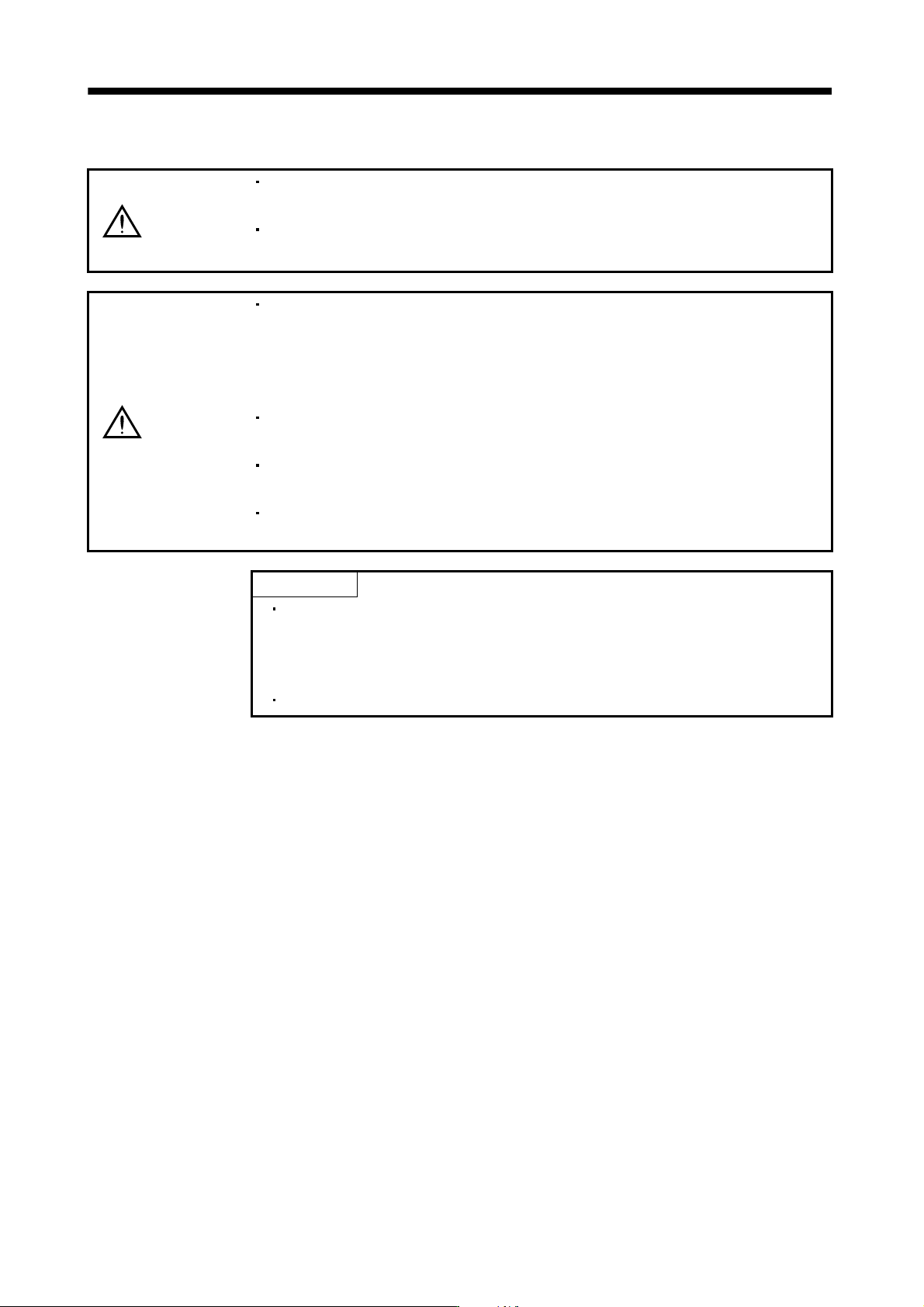
WARNING
Insulate the connections of the power supply terminals. Not doing so can cause an
electric shock.
Magnetic contactor wiring connector on the converter unit CNP1.
Unattached state may cause an electric shock.
CAUTION
Always, connect the magnetic contactor (MC) between the main circuit power
supply and L
1, L2, and L3 of the converter unit, and configure to shut off the power
supply on the side of the converter unit power supply. If the magnetic contactor
(MC) is not connected, a large current keeps flowing and may cause a fire when
the converter unit or the drive unit malfunctions.
Use the trouble signal to switch power off. Otherwise, a regenerative transistor fault
or the like may overheat the regenerative resistor, causing a fire.
Connect the power supply phases (U, V, W) of the servo amplifier and servo motor
correctly. Not doing so can cause the servo motor to run abnormally.
Do not connect a 3-phase 200V power supply or a 3-phase 400V power supply
directly to the servo motor. Doing so can cause a failure.
POINT
Magnetic contactor control connector (CNP1) of the converter unit can be
made valid or invalid with parameter No.PA02 of the converter unit. Refer to
section 13.3.1 and 13.3.6 for details of CNP1 and section 13.5 for the
parameter settings.
When using the external dynamic brake, refer to section 11.6 and 13.9.3.