sh030051g.pdf - 第6页
A - 5 (3) Test run adjustment CAUTION Before operation, check the parameter settings. Improp er settings may cause some machines to perform unexpected operation. The parameter settings must not be changed excessively. Op…
A - 4
CAUTION
Provide adequate protection to prevent screws and other conductive matter, oil and other combustible
matter from entering the converter unit, servo amplifier (drive unit), and servo motor.
Do not drop or strike converter unit, servo amplifier (drive unit), or servo motor. Isolate from all impact
loads.
Securely attach the servo motor to the machine. If attach insecurely, the servo motor may come off during
operation.
The servo motor with reduction gear must be installed in the specified direction to prevent oil leakage.
Take safety measures, e.g. provide covers, to prevent accidental access to the rotating parts of the servo
motor during operation.
Never hit the servo motor or shaft, especially when coupling the servo motor to the machine. The encoder
may become faulty.
Do not subject the servo motor shaft to more than the permissible load. Otherwise, the shaft may break.
When the equipment has been stored for an extended period of time, consult Mitsubishi.
(2) Wiring
CAUTION
Wire the equipment correctly and securely. Otherwise, the servo motor may operate unexpectedly.
Do not install a power capacitor, surge absorber or radio noise filter (FR-BIF (-H) option) between the
servo motor and servo amplifier (drive unit).
Connect the wires to the correct phase terminals (U, V, W) of the servo amplifier (drive unit) and servo
motor. Otherwise, the servo motor does not operate properly.
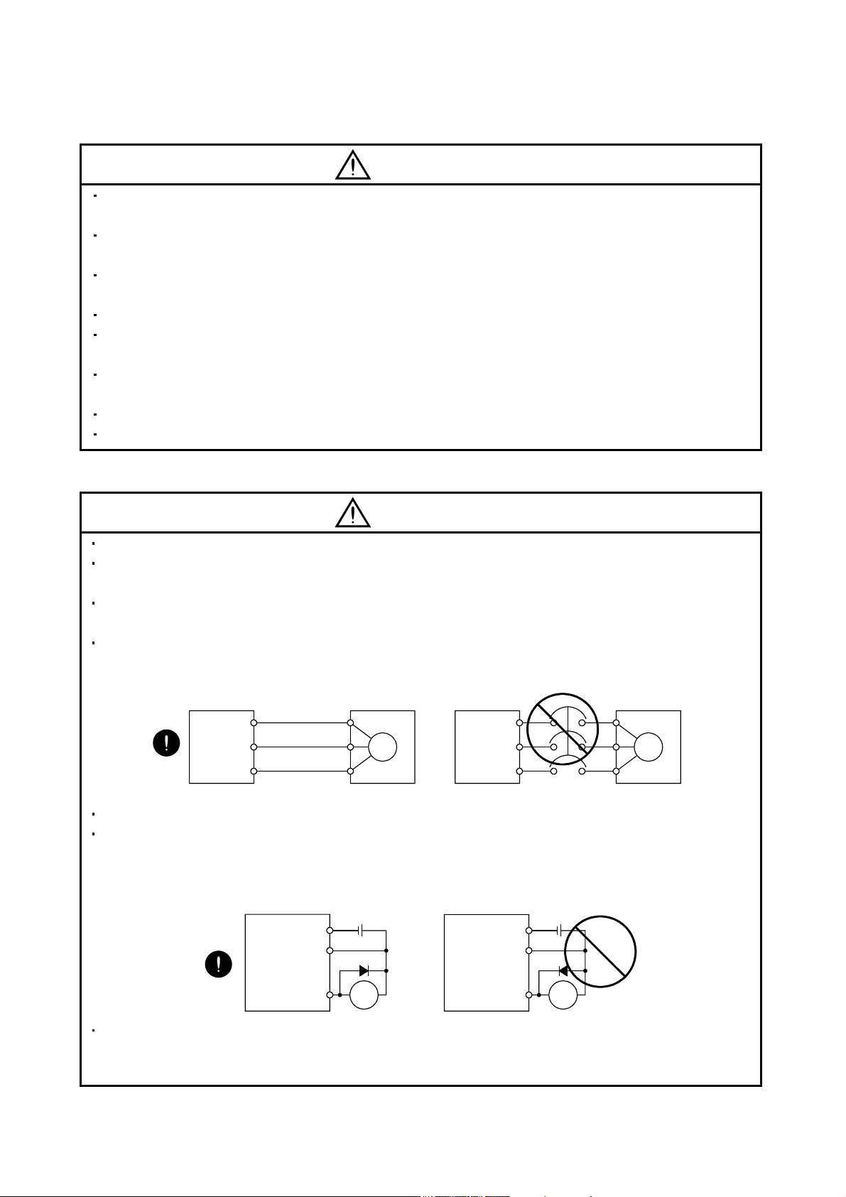
Connect the servo motor power terminal (U, V, W) to the servo motor power input terminal (U, V, W)
directly. Do not let a magnetic contactor, etc. intervene.
U
Servo motor
M
V
W
U
V
W
U
M
V
W
U
V
W
Servo amplifier
(drive unit)
Servo motor
Servo amplifier
(drive unit)
Do not connect AC power directly to the servo motor. Otherwise, a fault may occur.
The surge absorbing diode installed on the DC output signal relay of the servo amplifier (drive unit) must
be wired in the specified direction. Otherwise, the forced stop (EM1) and other protective circuits may not
operate.
Control
output
signal
Control
output
signal
RA
DOCOM
DICOM
24VDC
RA
DOCOM
DICOM
24VDC
Servo amplifier
(drive unit)
Servo amplifier
(drive unit)
When the cable is not tightened enough to the terminal block (connector), the cable or terminal block
(connector) may generate heat because of the poor contact. Be sure to tighten the cable with specified
torque.
A - 5
(3) Test run adjustment
CAUTION
Before operation, check the parameter settings. Improper settings may cause some machines to perform
unexpected operation.
The parameter settings must not be changed excessively. Operation will be insatiable.
(4) Usage
CAUTION
Provide an external emergency stop circuit to ensure that operation can be stopped and power switched
off immediately.
Any person who is involved in disassembly and repair should be fully competent to do the work.
Before resetting an alarm, make sure that the run signal of the servo amplifier (drive unit) is off to prevent
an accident. A sudden restart is made if an alarm is reset with the run signal on.
Do not modify the equipment.
Use a noise filter, etc. to minimize the influence of electromagnetic interference, which may be caused by
electronic equipment used near the converter unit and servo amplifier (drive unit).
Burning or breaking a converter unit and servo amplifier (drive unit) may cause a toxic gas. Do not burn or
break a converter unit and servo amplifier (drive unit).
Use the converter unit and servo amplifier (drive unit) with the specified servo motor.
The electromagnetic brake on the servo motor is designed to hold the motor shaft and should not be used
for ordinary braking.
For such reasons as service life and mechanical structure (e.g. where a ball screw and the servo motor
are coupled via a timing belt), the electromagnetic brake may not hold the motor shaft. To ensure safety,
install a stopper on the machine side.
A - 6
(5) Corrective actions
CAUTION
When it is assumed that a hazardous condition may take place at the occur due to a power failure or a
product fault, use a servo motor with an electromagnetic brake or an external brake mechanism for the
purpose of prevention.
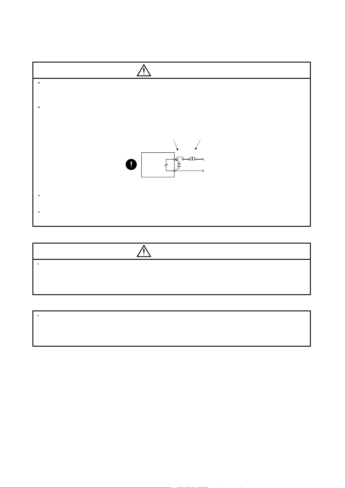
Configure the electromagnetic brake circuit so that it is activated not only by the servo amplifier (drive unit)
signals but also by an external forced stop (EM1).
EM1RA
24VDC
Contacts must be open when
servo-off, when an trouble (ALM)
and when an electromagnetic brake
interlock (MBR).
Electromagnetic brake
Servo motor
Circuit must be
opened during
forced stop (EM1).
When any alarm has occurred, eliminate its cause, ensure safety, and deactivate the alarm before
restarting operation.
When power is restored after an instantaneous power failure, keep away from the machine because the
machine may be restarted suddenly (design the machine so that it is secured against hazard if restarted).
(6) Maintenance, inspection and parts replacement
CAUTION
With age, the electrolytic capacitor of the converter unit and servo amplifier (drive unit) will deteriorate. To
prevent a secondary accident due to a fault, it is recommended to replace the electrolytic capacitor every
10 years when used in general environment.
Please consult our sales representative.
(7) General instruction
To illustrate details, the equipment in the diagrams of this Specifications and Instruction Manual may have
been drawn without covers and safety guards. When the equipment is operated, the covers and safety
guards must be installed as specified. Operation must be performed in accordance with this Specifications
and Instruction Manual.