sh030051g.pdf - 第408页
App. - 5 A PPENDI X App. 5 MR-J3-200B-RT servo amplifier Connectors (CNP1, CNP2, and CNP3) and appearance of MR-J3-200B servo amplifier have been changed from January 2008 production. Model name of the existi ng servo am…

App. - 4
A
PPENDI
X
App. 4 Change of connector sets to the RoHS compatible products
The following connector sets have been changed to RoHS compliant since June 2014.
RoHS compliant and non-RoHS compliant connector sets may be mixed based on availability.
Only the components of the connector set that have changed are listed below.
Model Current Product RoHS Compatible Product
MR-J3SCNS
MR-ECNM
Amplifier connector (3M or equivalent of 3M)
36210-0100JL (Receptacle) (Note)
Amplifier connector (3M or equivalent of 3M)
36210-0100PL (Receptacle)
MR-PWCNS4 Power supply connector (DDK)
CE05-6A18-10SD-B-BSS (Connector and Back shell)
CE3057-10A-1 (D265) (Cable clump)
Power supply connector (DDK)
CE05-6A18-10SD-D-BSS (Connector and Back shell)
CE3057-10A-1-D (Cable clump)
MR-PWCNS5 Power supply connector (DDK)
CE05-6A22-22SD-B-BSS (Connector and Back shell)
CE3057-12A-1 (D265) (Cable clump)
Power supply connector (DDK)
CE05-6A22-22SD-D-BSS (Connector and Back shell)
CE3057-12A-1-D (Cable clump)
MR-PWCNS3 Power supply connector (DDK)
CE05-6A32-17SD-B-BSS (Connector and Back shell)
CE3057-20A-1 (D265) (Cable clump)
Power supply connector (DDK)
CE05-6A32-17SD-D-BSS (Connector and Back shell)
CE3057-20A-1-D (Cable clump)
MR-PWCNS1 Power supply connector (DDK)
CE05-6A22-23SD-B-BSS (Connector and Back shell)
CE3057-12A-2 (D265) (Cable clump)
Power supply connector (DDK)
CE05-6A22-23SD-D-BSS (Connector and Back shell)
CE3057-12A-2-D (Cable clump)
MR-PWCNS2 Power supply connector (DDK)
CE05-6A24-10SD-B-BSS (Connector and Back shell)
CE3057-16A-2 (D265) (Cable clump)
Power supply connector (DDK)
CE05-6A24-10SD-D-BSS (Connector and Back shell)
CE3057-16A-2-D (Cable clump)
MR-BKCN Electromagnetic brake connector
MS3106A10SL-4S(D190) (Plug, DDK)
Electromagnetic brake connector
D/MS3106A10SL-4S(D190) (Plug, DDK)
MR-CCN1 Amplifier connector (3M or equivalent of 3M)
10120-3000VE (connector)
Amplifier connector (3M or equivalent of 3M)
10120-3000PE (connector)
Note. RoHS compatible 36210-0100FD may be packed with current connector sets.
App. - 5
A
PPENDI
X
App. 5 MR-J3-200B-RT servo amplifier
Connectors (CNP1, CNP2, and CNP3) and appearance of MR-J3-200B servo amplifier have been changed
from January 2008 production. Model name of the existing servo amplifier is changed to MR-J3-200B-RT. The
difference between new MR-J3-200B servo amplifier and existing MR-J3-200B-RT servo amplifier is described
in this appendix. Sections within parentheses in the following sections indicate corresponding sections of the
instruction manual.
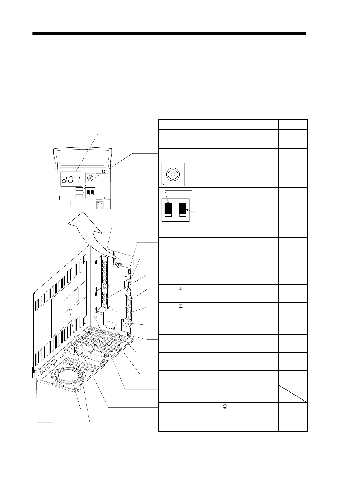
App. 5.1 Parts identification (1.7.1 Parts identification)
7
9
6
8
5
4
3
2
1
0
F
E
D
C
B
A
12
ON 4F
SW1
SW2
TEST
Fixed part
(3 places)
Cooling fan
Used to set the axis No. of servo amplifier.
Rotary axis setting switch (SW1)
SW2
Test operation select switch (SW2-1)
Used to perform the test operation
mode by using MR Configurator.
Spare (Be sure to set to the "Down"
position).
Detailed
explanation
Section 3.13
SW1
Section 3.13
Name/Application
12
Display
The 3-digit, seven-segment LED shows the servo
status and alarm number.
Main circuit power supply connector (CNP1)
Connect the input power supply.
USB communication connector (CN5)
Connect the personal computer.
I/O signal connector (CN3)
Used to connect digital I/O signals.
More over an analog monitor is output.
Section 3.2
Section 3.4
SSCNET cable connector (CN1A)
Used to connect the servo system controller or the front
axis servo amplifier.
SSCNET cable connector (CN1B)
Used to connect the rear axis servo amplifier. For the final
axis, puts a cap.
Encoder connector (CN2)
Used to connect the servo motor encoder.
Charge lamp
Lit to indicate that the main circuit is charged. While
this lamp is lit, do not reconnect the cables.
Battery connector (CN4)
Used to connect the battery for absolute position data
backup.
Battery holder
Contains the battery for absolute position data backup.
Protective earth (PE) terminal ( )
Ground terminal.
Rating plate
7
6
5
4
3
2
1
0
F
E
D
C
B
A
9
8
Chapter 4
Section 3.1
Section 3.3
Section 11.8
Section 3.2
Section 3.4
Control circuit connector (CNP2)
Connect the control circuit power supply/regenerative
option.
Section 3.1
Section 3.3
Section 3.2
Section 3.4
Servo motor power connector (CNP3)
Connect the servo motor.
Section 3.1
Section 3.3
Section 3.4
Section 11.1
Section 11.9
Chapter 12
Section 12.3
Section 3.1
Section 3.3
Section 1.5
App. - 6
A
PPENDI
X
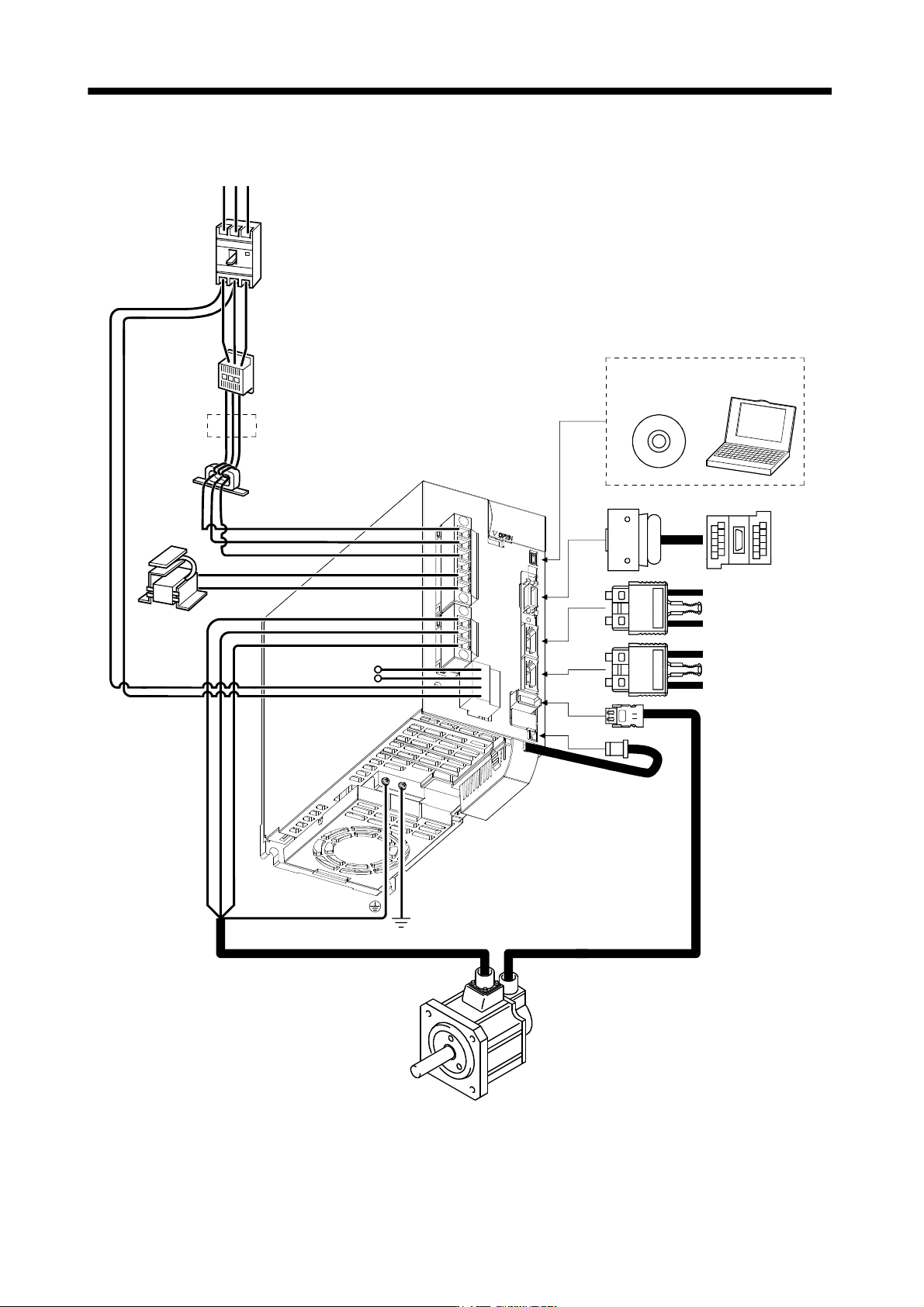
App. 5.2 Configuration including auxiliary equipment (1.8 Configuration including auxiliary equipment)
R S T
P
C
L
21
P
1
P
2
UV
W
L11
L
1
L
2
L3
CN5
CN3
CN2
CN1A
CN1B
CN4
Line noise filter
(FR-BLF)
(Note 3)
Power supply
Magnetic
contactor
(MC)
No-fuse breaker
(NFB) or fuse
Regenerative
option
(Note 2)
Power factor
improving DC
reactor
(FR-BEL)
(Note 2)
Servo amplifier
Junction
terminal
block
MR Configurator
Personal
computer
(Note 1)
Battery
MR-J3BAT
Servo system
controller or Front axis
servo amplifier CN1B
Rear servo amplifier
CN1A or Cap
Servo motor
Note 1. The battery (option) is used for the absolute position detection system in the position control mode.
2. The AC reactor can also be used. In this case, the DC reactor cannot be used. When not using DC reactor, short P
1-P2.
3. Refer to section 1.3 for the power supply specification.