sh030051g.pdf - 第204页
10 - 9 10. CHARACTERISTIC S 10.3.2 The dynamic brake at the load in ertia moment Use the dynamic brake under the load inertia momen t rati o indicated in the following table . If the load iner tia moment is higher than t…
10 - 8
10. CHARACTERISTICS
Ti
m
e
c
o
n
s
t
a
n
t
[
m
s
]
0
0
52
500 1000 1500 2000
202
200
152
102
160
120
80
40
302
Speed[r/min]
HC-LP series
(b) 400V class servo motor
5024
0 1000 2000 3000
75
60
45
30
15
0
90
7024
1524
3524
1024
524
2024
Ti
m
e
c
o
n
s
t
a
n
t
[
m
s
]
Speed[r/min]
Ti
m
e
c
o
n
s
t
a
n
t
[
m
s
]
0 400 800 1200
35
0
30
25
20
15
10
5
Speed[r/min]
8014
15K14
12K14
20K14
6014
HA-SP2000r/min series HA-LP1000r/min series
Ti
m
e
c
o
n
s
t
a
n
t
[
m
s
]
0 500 1000 1500
20
16
12
8
4
0
Speed[r/min]
11K1M4
15K1M4
701M4
22K1M4
Ti
m
e
c
o
n
s
t
a
n
t
[
m
s
]
0
500 1000 1500 20000
40
35
30
25
20
15
10
5
11K24
22K2
15K24
Speed[r/min]
HA-LP1500r/min series HA-LP2000r/min series
10 - 9
10. CHARACTERISTICS
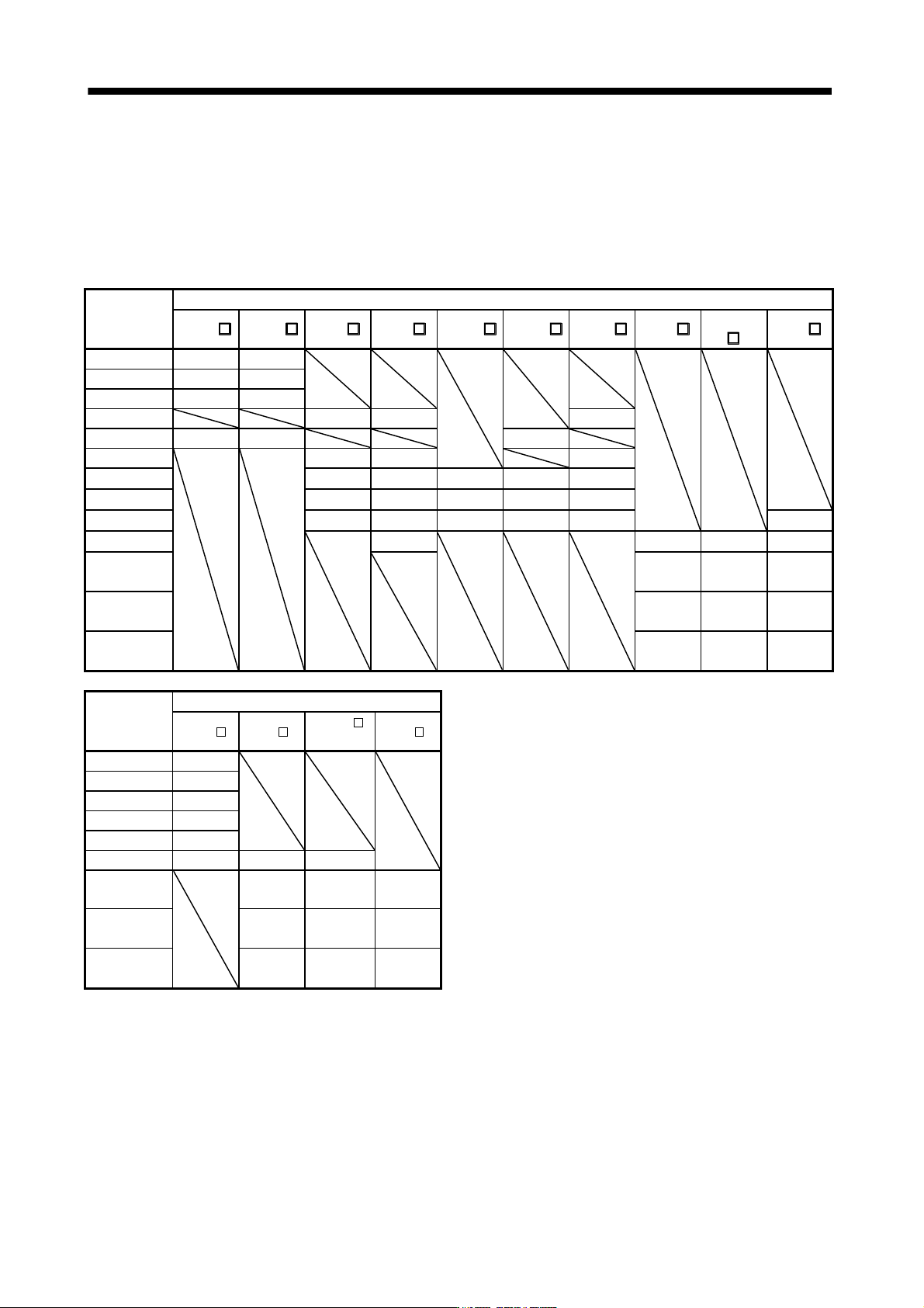
10.3.2 The dynamic brake at the load inertia moment
Use the dynamic brake under the load inertia moment ratio indicated in the following table. If the load inertia
moment is higher than this value, the built-in dynamic brake may burn. If there is a possibility that the load
inertia moment may exceed the value, contact Mitsubishi.
The values of the load inertia moment ratio in the table are the values at the maximum rotation speed of the
servo motor.
Servo
amplifier
Servo motor
HF-KP HF-MP HF-SP 1 HF-SP 2 HC-RP HC-UP HC-LP HA-LP 1
HA-
LP
1M
HA-LP
2
MR-J3-10B(1) 30 30
MR-J3-20B(1) 30 30
MR-J3-40B(1) 30 30
MR-J3-60B 30 30 30
MR-J3-70B 30 30 30
MR-J3-100B
30 30 30
MR-J3-200B 30 30 30 30 30
MR-J3-350B 16 16 16 16 16
MR-J3-500B 15 15 15 15 15 15
MR-J3-700B
5 (Note 1)
5 (Note 1) 5 (Note 1) 5 (Note 1)
MR-J3-11KB
(Note 2)
30 30 30
MR-J3-15KB
(Note 2)
30 30 30
MR-J3-22KB
(Note 2)
30 30 30
Servo
amplifier
Servo motor
HF-SP 4 HA-LP 14
HA-LP
1M4
HA-LP
24
MR-J3-60B4 5 (Note 1)
MR-J3-100B4 5 (Note 1)
MR-J3-200B4 5 (Note 1)
MR-J3-350B4 5 (Note 1)
MR-J3-500B4 5 (Note 1)
MR-J3-700B4 5 (Note 1) 10 10
MR-J3-11KB4
(Note 2)
30 30 30
MR-J3-15KB4
(Note 2)
30 30 30
MR-J3-22KB4
(Note 2)
30 30 30
Note 1. The load inertia moment ratio is 15 at the rated rotation speed.
2. When the external dynamic brake is used.
10 - 10
10. CHARACTERISTICS
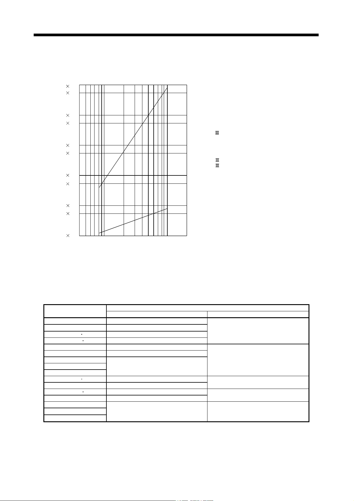
10.4 Cable flexing life
The flexing life of the cables is shown below. This graph calculated values. Since they are not guaranteed
values, provide a little allowance for these values.
1 10
7
5 10
7
1 10
8
5 10
6
1 10
6
5 10
5
1 10
5
5 10
4
1 10
4
5 10
3
1 10
3
a
b
F
l
e
x
i
n
g
l
i
f
e
[
t
i
m
e
s
]
4 7 10 20 40 70 100 200
Flexing radius [mm]
a : Long flex life encoder cable
Long flex life motor power cable
Long flex life motor brake cable
SSCNET cable using long distance cable
b : Standard encoder cable
Standard motor power cable
Standard motor brake cable
SSCNET cable using inside panel standard cord
SSCNET cable using outside panel standard cable
10.5 Inrush currents at power-on of main circuit and control circuit
The following table indicates the inrush currents (reference data) that will flow when the maximum permissible
voltage (200V class: 253VAC, 400V class: 528VAC) is applied at the power supply capacity of 2500kVA and
the wiring length of 1m (3.28ft).
Servo amplifier
Inrush currents (A
0
-
p
)
Main circuit power supply (L
1
, L
2
, L
3
) Control circuit power supply (L
11
, L
21
)
MR-J3-10B1 to 40B1 38A (Attenuated to approx. 14A in 10ms)
20 to 30A
(Attenuated to approx. 0A in 1 to 2ms)
MR-J3-10B to 60B 30A (Attenuated to approx. 5A in 10ms)
MR-J3-70B 100B 54A (Attenuated to approx. 12A in 10ms)
MR-J3-200B 350B 120A (Attenuated to approx. 12A in 20ms)
MR-J3-500B 44A (Attenuated to approx. 20A in 20ms)
30A (Attenuated to approx. 0A in 3ms)
MR-J3-700B 88A (Attenuated to approx. 20A in 20ms)
MR-J3-11KB
235A (Attenuated to approx. 20A in 20ms)
MR-J3-15KB
MR-J3-22KB
MR-J3-60B4 100B4 100A (Attenuated to approx. 5A in 10ms)
40 to 50A
(Attenuated to approx. 0A in 2ms)
MR-J3-200B4 120A (Attenuated to approx. 12A in 20ms)
MR-J3-350B4 500B4 66A (Attenuated to approx. 10A in 20ms)
41A (Attenuated to approx. 0A in 3ms)
MR-J3-700B4 67A (Attenuated to approx. 34A in 20ms)
MR-J3-11KB4
325A (Attenuated to approx. 20A in 20ms) 45A (Attenuated to approx. 0A in 3ms)
MR-J3-15KB4
MR-J3-22KB4
Since large inrush currents flow in the power supplies, always use no-fuse breakers and magnetic contactors.
(Refer to section 11.12.)
When circuit protectors are used, it is recommended to use the inertia delay type that will not be tripped by an
inrush current.