sh030051g.pdf - 第113页
4 - 6 4. STARTUP (2) Indication list Indication Status Description A b Initializing Power of the servo amplifier was switched on at the condition that the power of servo system controller is O FF. The axis No. set to the…
4 - 5
4. STARTUP
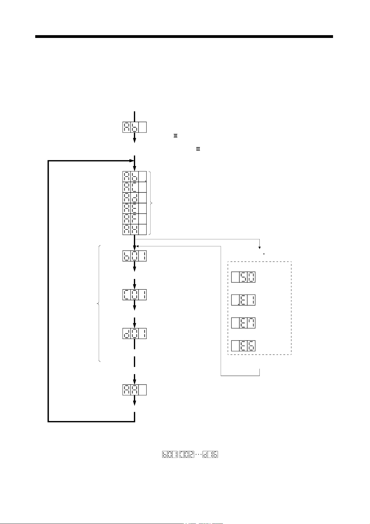
4.3 Servo amplifier display
On the servo amplifier display (three-digit, seven-segment display), check the status of communication with the
servo system controller at power-on, check the axis number, and diagnose a fault at occurrence of an alarm.
(1) Display sequence
Only alarm and warning No. are displayed, but no axis No. is displayed
Servo amplifier power ON
(Note 3)
At occurrence of overload
At occurrence of overload
warning (Note 2)
During controller
forced stop
During forced stop
Flicker
display
Alarm reset or
warning
1 axis 2 axis 16 axis
(Note 3)
(Note 3)
(Note 1)
When alarm warning
No. is displayed
Flicker
display
Flicker
display
Flicker
display
If warning other than E6 or E7 occurs during the servo on, flickering the
second place of decimal point indicates that it is during the servo on.
Note 1.
2.
3.
The right-hand segments of b01, c02 and d16 indicate the axis number.
(Below example indicates Axis1)
Initial data communication
with servo system controller
(Initialization communication)
When alarm occurs,
alarm code appears.
Ready ON
Ready OFF/servo OFF
Ready ON/servo OFF
Servo ON
Ready ON/servo ON
Servo system controller power ON
Ordinary operation
Servo system controller power OFF
Waiting for servo system controller
power to switch ON
(SSCNET communication)
Servo system controller power ON (SSCNET communication beginning)
4 - 6
4. STARTUP
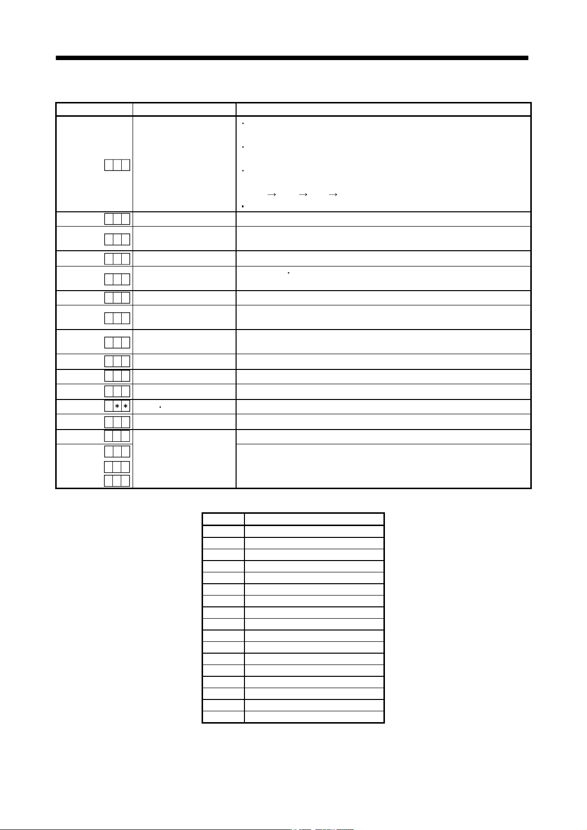
(2) Indication list
Indication Status Description
A b
Initializing
Power of the servo amplifier was switched on at the condition that the power of
servo system controller is OFF.
The axis No. set to the servo system controller does not match the axis No. set
with the rotary axis setting switch (SW1) of the servo amplifier.
A servo amplifier fault occurred or an error took place in communication with the
servo system controller. In this case, the indication changes.
"Ab "
"AC " "Ad " "Ab "
The servo system controller is faulty.
.
A
b
Initializing During initial setting for communication specifications
A C
Initializing
Initial setting for communication specifications completed, and then it synchronized
with servo system controller.
A d
Initializing During initial parameter setting communication with servo system controller
A E
Initializing
During motor
encoder information and telecommunication with servo system
controller
A F
Initializing During initial signal data communication with servo system controller
A H
Initializing completion
During the completion process for initial data communication with servo system
controller
A A
Initializing standby
The power supply of servo system controller is turned off during the power supply
of servo amplifier is on.
(Note 1)
b
# #
Ready OFF The ready off signal from the servo system controller was received.
(Note 1)
d
# #
Servo ON The ready off signal from the servo system controller was received.
(Note 1)
C
# #
Servo OFF The ready off signal from the servo system controller was received.
(Note 2)
Alarm
Warning The alarm No./warning No. that occurred is displayed. (Refer to section 9.1.)
8 88
CPU Error CPU watchdog error has occurred.
(Note 3)
0 0.b
(Note 3)
Test operation mode
JOG operation, positioning operation, programmed operation, DO forced output.
(Note 1)
# #.b
# #.d
# #.C
Motor-less operation
Note 1. ## denotes any of numerals 00 to 16 and what it means is listed below.
# Description
0 Set to the test operation mode.
1 First axis
2 Second axis
3 Third axis
4 Fourth axis
5 Fifth axis
6 Sixth axis
7 Seventh axis
8 Eighth axis
9 Ninth axis
10 Tenth axis
11 Eleventh axis
12 Twelfth axis
13 Thirteenth axis
14 Fourteenth axis
15 Fifteenth axis
16 Sixteenth axis
2. ** indicates the warning/alarm No.
3. Requires the MR Configurator.
4 - 7
4. STARTUP
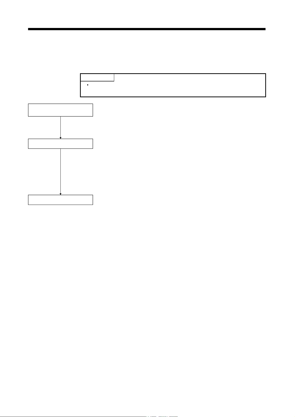
4.4 Test operation
Before starting actual operation, perform test operation to make sure that the machine operates normally.
Refer to section 4.2 for the power on and off methods of the servo amplifier.
POINT
If necessary, verify controller program by using motorless operation.
Refer to section 4.5.2 for the motorless operation.
Test operation of servo motor
alone in JOG operation of test
operation mode
Test operation of servo motor
alone by commands
Test operation with servo motor
and machine connected
In this step, confirm that the servo amplifier and servo motor operate normally.
With the servo motor disconnected from the machine, use the test operation
mode and check whether the servo motor rotates correctly. Refer to section
4.5 for the test operation mode.
In this step, confirm that the servo motor rotates correctly under the
commands from the controller.
Make sure that the servo motor rotates in the following procedure.
Give a low speed command at first and check the rotation direction, etc. of the
servo motor.
If the servo motor does not operate in the intended direction, check the input
signal.
In this step, connect the servo motor with the machine and confirm that the
machine operates normally under the commands from the command device.
Make sure that the servo motor rotates in the following procedure.
Give a low speed command at first and check the operation direction, etc. o
f
the machine. If the machine does not operate in the intended direction, check
the input signal. In the status display, check for any problems of the servo
motor speed, command pulse frequency, load ratio, etc.
Then, check automatic operation with the program of the command device.