sh030051g.pdf - 第358页
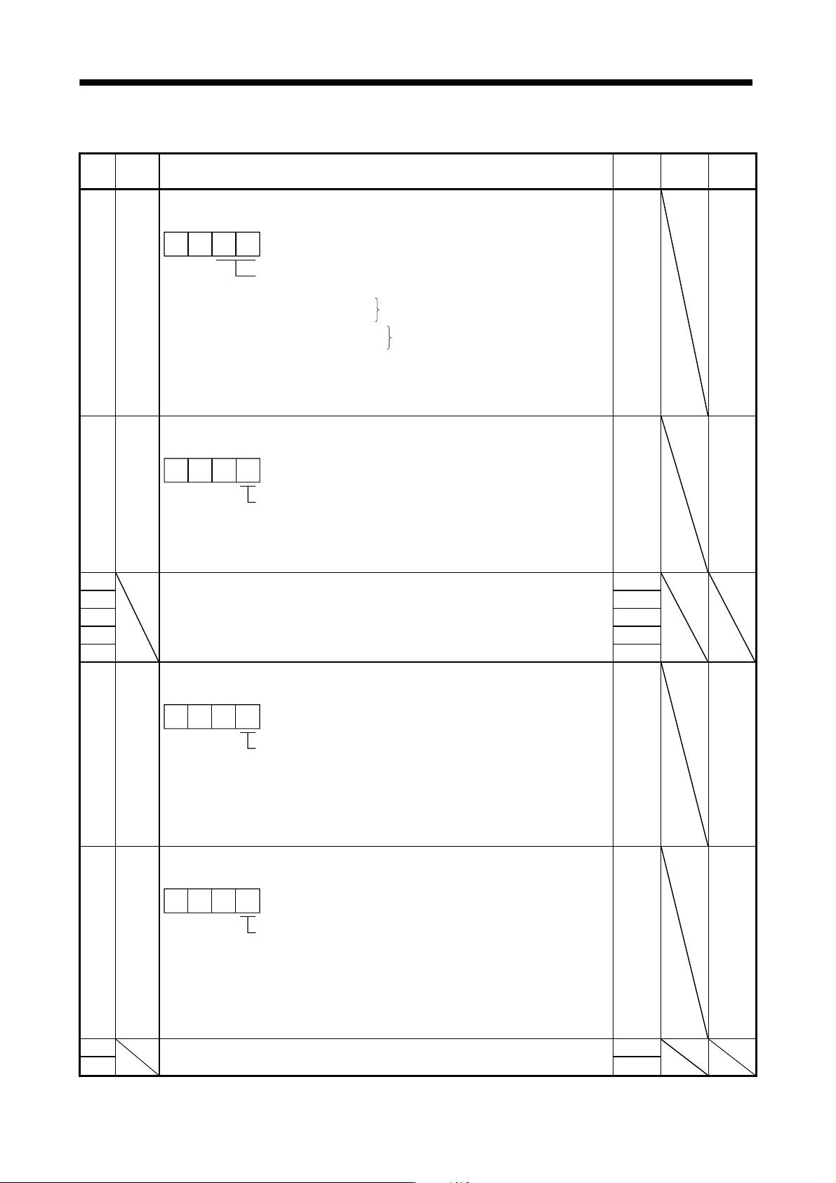
13 - 57 13. SERVO AMPLIFIERS WI TH A LARGE CAPACITY ( 30k TO 55kW ) No. Symbol Name and function Initial value Unit Setting range PA12 *DIF Input filter setting Select the input filter. Input signal filt er If external i…
13 - 56
13. SERVO AMPLIFIERS WITH A LARGE CAPACITY
(
30k TO 55kW
)
13.5.2 List of details
No. Symbol Name and function
Initial
value
Unit
Setting
range
PA01 *REG Regenerative option
Used to select the regenerative option.
Select the regenerative option.
00: No used
01: MR-RB139
02: MR-RB137(3 pcs.)
11: MR-RB136-4
12: MR-RB138-4(3 pcs.)
"01" and "02" are the set values for the MR-J3-CR55K only, and "11"
and "12" are those for the MR-J3-CR55K4 only.
Wrong setting will result in parameter alarm (A.37).
00
Only for MR-J3-CR55K
Only for MR-J3-CR55K4
0000h Refer to
Name
and
function
column.
PA02 *MCC Magnetic contactor drive output selection
Used to select the output of the magnetic contactor drive power supply.
Used to select the output of the magnetic contactor drive power
supply.
0: No used
1: Used
000
0001h Refer to
Name
and
function
column.
PA03 For manufacturer setting 0001h
PA04 Do not change this value by any means. 0
PA05 100
PA06 0
PA07 100
PA08 *DMD Status display selection
Used to select the status display shown at power-on.
Status display of converter unit display section at power-on.
0: Status
1: Bus voltage
2: Effective load ratio
3: Peak load ratio
4: Regenerative load ratio
000
0000h Refer to
Name
and
function
column.
PA09 *BPS Alarm history clear
Used to clear the alarm history.
Alarm history clear
0: Invalid
1: Valid
When alarm history clear is made valid, the alarm history is cleared
at next power-on.
After the alarm history is cleared, the setting is automatically made
invalid (reset to 0).
000
0000h Refer to
Name
and
function
column.
PA10 For manufacturer setting 0
PA11 Do not change this value by any means. 0000h
13 - 57
13. SERVO AMPLIFIERS WITH A LARGE CAPACITY
(
30k TO 55kW
)
No. Symbol Name and function
Initial
value
Unit
Setting
range
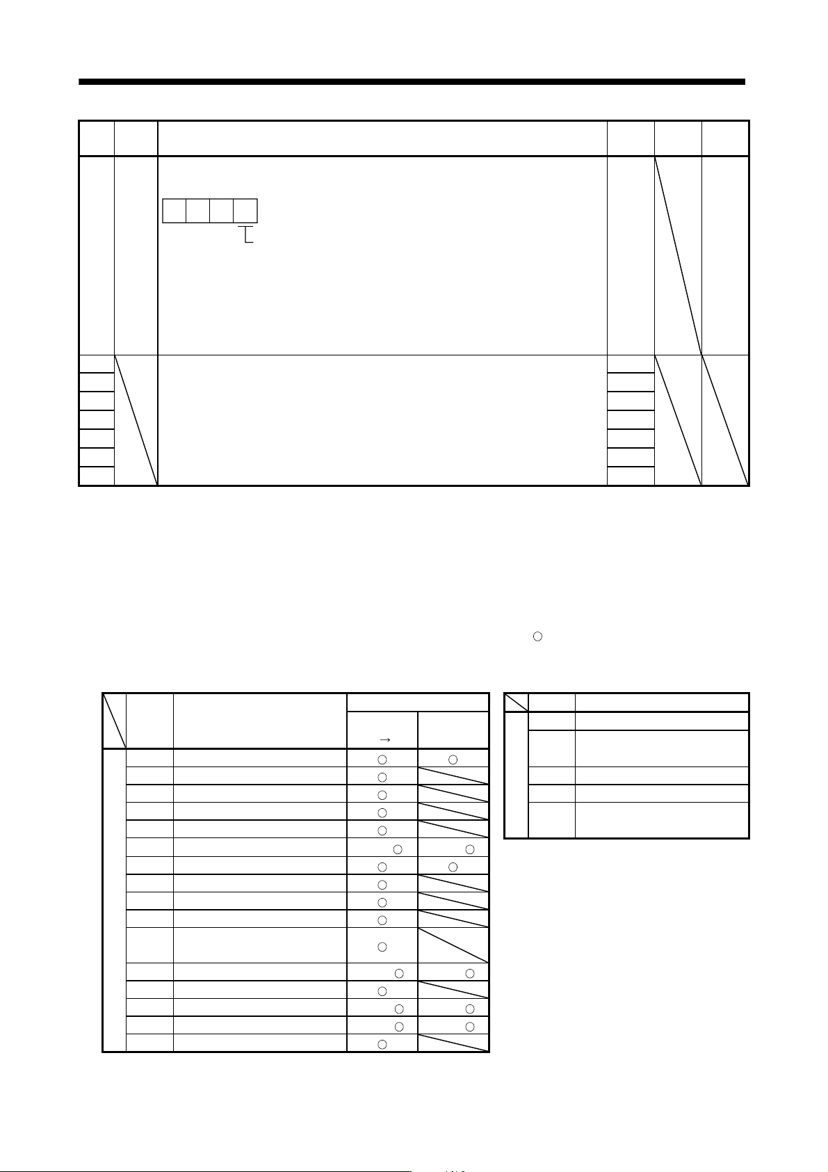
PA12 *DIF Input filter setting
Select the input filter.
Input signal filter
If external input signal causes chattering due to noise, etc., input
filter is used to suppress it.
0: None
1: 1.777[ms]
2: 3.555[ms]
3: 5.333[ms]
000
0002h Refer to
Name
and
function
column.
PA13 For manufacturer setting 0000h
PA14 Do not change this value by any means. 0000h
PA15 0000h
PA16 0000h
PA17 0000h
PA18 0000h
PA19 0000h
13.6 Troubleshooting
13.6.1 Converter unit
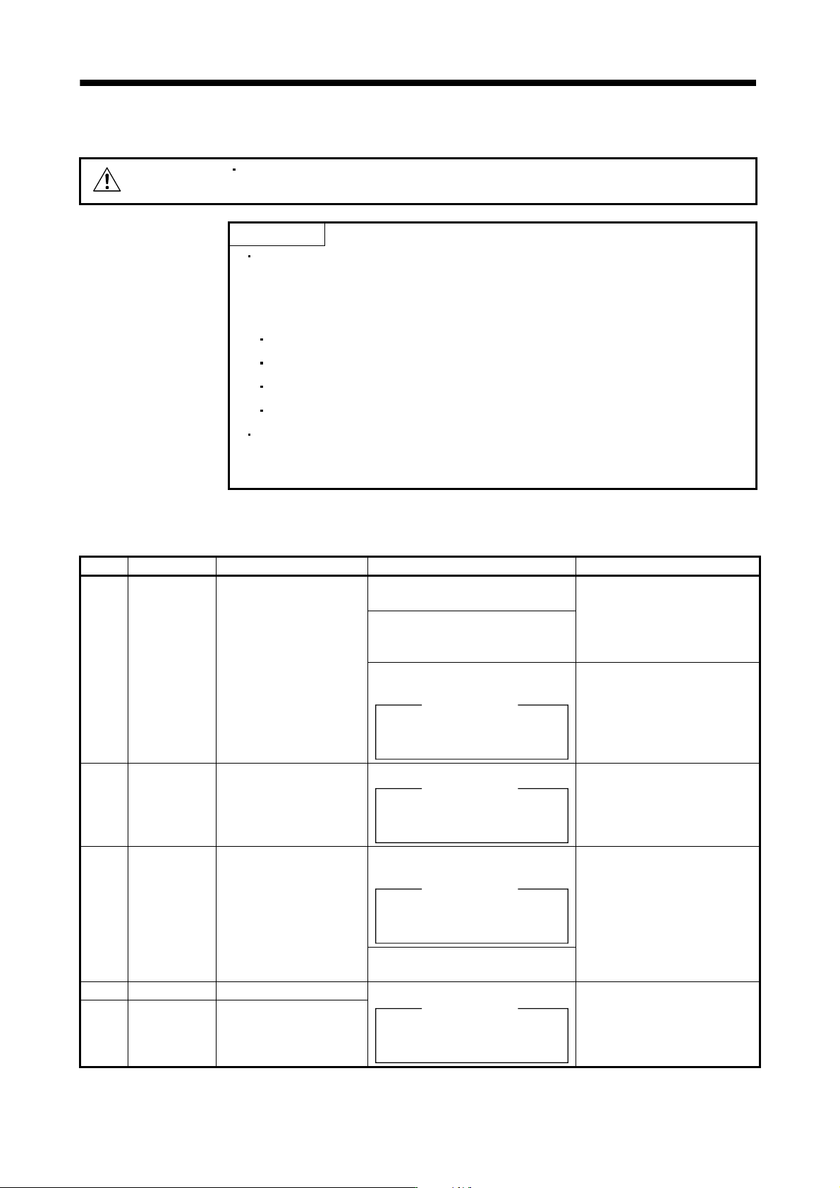
(1) Alarms and warning list
When a fault occurs during operation, the corresponding alarm or warning is displayed. If any alarm or
warning has occurred, refer to (2) or (3) of this section and take the appropriate action.
Switch power off, then on to deactivate the alarm. The alarms marked "
" in the alarm deactivation column
of the table can be deactivated by pressing the "RES" key of the converter unit side parameter unit or
switching on the reset signal (RES).
Display Name
Alarm deactivation Display Name
Power Error
Warning
A.91 Overheat warning
OFF ON reset
A.E0
Excessive regenerative load
Alarm
A.10 Undervoltage warning
A.12 Memory error1 (RAM) A.E1 Over load warning
A.15 Memory error2 (EEP-ROM) A.E6 Converter forced stop warning
A.17 Board error
A.E8
Cooling fan speed reduction
A.19 Memory error3 (Flash-ROM) warning
A.30 Regenerative error (Note) (Note)
A.33 Over voltage
A.37 Parameter error
A.38 MC drive circuit error
A.39 Open phase
A.3A
Inrush current suppressor circuit
error
A.45 Main circuit device overheat (Note) (Note)
A.47 Cooling fan error
A.50 Over load 1 (Note) (Note)
A.51 Over load 2 (Note) (Note)
888 Watchdog
Note. Deactivate the alarm about 30 minutes of cooling time after removing the cause of occurrence.
13 - 58
13. SERVO AMPLIFIERS WITH A LARGE CAPACITY
(
30k TO 55kW
)
(2) Remedies for alarms
CAUTION
When any alarm has occurred, eliminate its cause, ensure safety, then reset the
alarm, and restart operation. Otherwise, injury may occur.
POINT
When any of the following alarms has occurred, always remove its cause and
allow about 30 minutes for cooling before resuming operation. If operation is
resumed by switching control circuit power off, then on to reset the alarm, the
converter unit and regenerative option may become faulty.
Regenerative error (A.30)
Over load 1 (A.50)
Over load 2 (A.51)
Main circuit device overheat (A.45)
The alarm can be deactivated by switching the power off, then on or by the
error reset command from the host controller. Refer to (1) in this section for
details.
When an alarm occurs, the trouble (ALM) signal switches off and the display section shows the alarm number.
Remove the cause of the alarm in accordance with this section.
Display Name Definition Cause Action
A.10 Undervoltage Power supply voltage
dropped.
1. Instantaneous control power failure
occurred for more than 60ms.
Review the power supply.
2. Shortage of power supply capacity
caused the power supply voltage to
drop at start, etc.
3. Failure of the part in the converter
unit.
Checking method
Alarm (A.10) occurs if power is
switched on after connectors
disconnected.
Change the Converter unit.
A.12 Memory error 1
(RAM)
RAM memory fault Failure of the part in the converter unit.
Checking method
Alarm (A.12) occurs if power is
switched on after connectors
disconnected.
Change the converter unit.
A.15 Memory error 2
(EEP-ROM)
EEP-ROM fault 1. Failure of the part in the converter
unit.
Checking method
Alarm (A.15) occurs if power is
switched on after connectors
disconnected.
Change the converter unit.
2. The number of write times to EEP-
ROM exceeded 100,000.
A.17 Board error CPU/parts fault Failure of the part in the converter unit. Change the converter unit.
A.19 Memory error 3
(Flash-ROM)
ROM memory fault
Checking method
Alarm (A.17/A.19) occurs if power is
switched on after connectors
disconnected.