sh030051g.pdf - 第215页
11 - 10 11. OPTIONS AND AUXILI ARY EQUIPMENT (a) Connection of servo amplifier and servo motor Servo motor HF-MP HF-KP 1) MR-EKCBL M-L MR-EKCBL M-H MR-J3JCBL03M-L Cabl e le ngth: 0.3m 2) Servo amplifier CN2 Cable model 1…
11 - 9
11. OPTIONS AND AUXILIARY EQUIPMENT
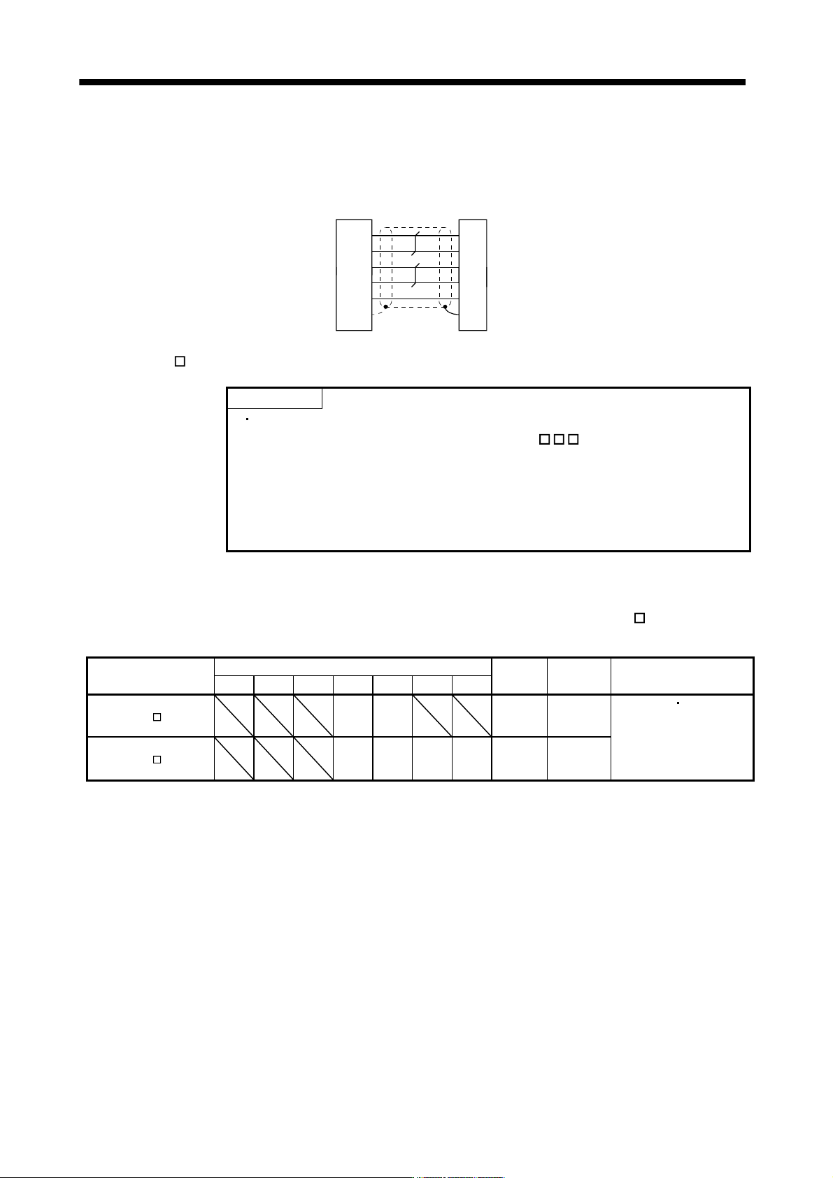
(b) Cable internal wiring diagram
Servo amplifier
side connector
Encoder side
connector
Plate
MR-J3ENCBL2M-L/-H
MR-J3ENCBL5M-L/-H
MR-J3ENCBL10M-L/-H
P5
LG
1
2
MR
MRR
3
4
2
3
9
SD
5
4
6
9
LG
MR
MRR
SHD
P5
BATBAT
(2) MR-EKCBL
M-L/H
POINT
The following encoder cables are of four-wire type. When using any of these
encoder cables, set parameter No.PC04 to "1
" to select the four-wire
type.
MR-EKCBL30M-L
MR-EKCBL30M-H
MR-EKCBL40M-H
MR-EKCBL50M-H
The servo amplifier and servo motor cannot be connected with these cables only. The servo motor side
encoder cable (MR-J3JCBL03M-A1-L or MR-J3JCBL03M-A2-L) is required.
The numerals in the Cable Length field of the table are the symbols entered in the
part of the cable
model. The cables of the lengths with the symbols are available.
Cable model
Cable length
Protective
structure
Flex life Application
2m 5m 10m 20m 30m 40m 50m
MR-EKCBL M-L 20
(Note)
30
IP20 Standard
For HF-MP
HF-KP servo
motor
Use in combination with
MR-J3JCBL03M-A1-L or
MR-J3JCBL03M-A2-L.
MR-EKCBL M-H 20
(Note)
30
(Note)
40
(Note)
50
IP20
Long flex
life
Note. Four-wire type cable.
11 - 10
11. OPTIONS AND AUXILIARY EQUIPMENT
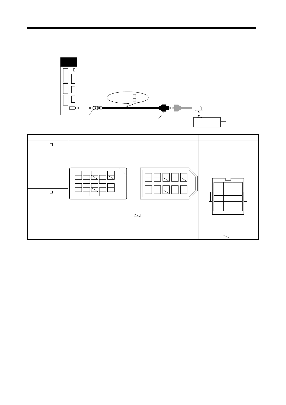
(a) Connection of servo amplifier and servo motor
Servo motor
HF-MP
HF-KP
1)
MR-EKCBL M-L
MR-EKCBL M-H
MR-J3JCBL03M-L
Cable length: 0.3m
2)
Servo amplifier
CN2
Cable model 1) For CN2 connector 2) For encoder connector
MR-EKCBL M-L
Receptacle: 36210-0100PL
Shell kit: 36310-3200-008
(3M)
Connector set: 54599-1019(Molex) Housing: 1-172161-9
Crimping pin: 170359-1
(Tyco Electronics or equivalent)
Cable clamp: MTI-0002
(Toa Electric Industries)
MR
123
MRR BAT
MD
456
MDR
P5
789
LG SHD
Signal layout
View seen from wiring side.
CONT
Note. Keep open the pin shown
with an
.
1 3 7 9
42 86 10
5
(Note) Signal layout
View seen from wiring side.
or
4
MRR
2
LG
8
6
1
P5
5
10
3
MR
7
9
BAT
(Note) Signal layout
View seen from wiring side.
MRR
LG
P5 MR
BAT
MDR
MD
MDR
MD
Note. Keep open the pins shown with . Especially, pin 10 is provided
for manufacturer adjustment. If it is connected with any other pin, the
servo amplifier cannot operate normally.
MR-EKCBL M-H
11 - 11
11. OPTIONS AND AUXILIARY EQUIPMENT
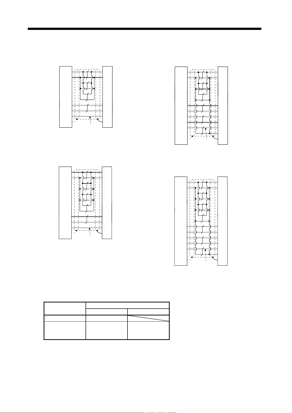
(b) Internal wiring diagram
MR-EKCBL20M-L
Servo amplifier side Encoder side
P5
LG
1
2
MR
MRR
3
4
3
7
9
SD Plate
1
2
8
9
P5G
MR
MRR
SHD
P5E
BATBAT
(Note)
MR-EKCBL30M-L
Servo amplifier side Encoder side
P5
LG
1
2
MR
MRR
3
4
MDR 8 5
3
7
4
MD 7
9
SD
1
2
8
9
P5G
MR
MRR
MDR
MD
SHD
P5E
6CONT
BATBAT
Plate
(Note)
MR-EKCBL20M-H
Servo amplifier side Encoder side
P5
LG
1
2
MR
MRR
3
4
3
7
9
SD
1
2
8
9
P5G
MR
MRR
SHD
P5E
BATBAT
(Note)
Plate
MR-EKCBL30M-H
MR-EKCBL40M-H
MR-EKCBL50M-H
Servo amplifier side Encoder side
P5
LG
1
2
MR
MRR
3
4
MDR 8 5
3
7
4
MD 7
9
SD
1
2
8
9
P5G
MR
MRR
MDR
MD
SHD
P5E
6CONT
BATBAT
(Note)
Plate
Note. Always make connection for use in an absolute position detection system. Wiring is not necessary for use in an incremental
system.
When fabricating the cable, use the wiring diagram corresponding to the length indicated below.
Cable flex life
Applicable wiring diagram
Less than 10m 30m to 50m
Standard MR-EKCBL20M-L
Long flex life MR-EKCBL20M-H MR-EKCBL30M-H
MR-EKCBL40M-H
MR-EKCBL50M-H