sh030051g.pdf - 第151页
6 - 6 6. GENERAL GAIN ADJUSTMEN T 6.2.4 Response level setting in auto tuning mode Set the response (The first digit of par ameter No.PA09) of the whole servo system. As the response level setting is increased, the track…
6 - 5
6. GENERAL GAIN ADJUSTMENT
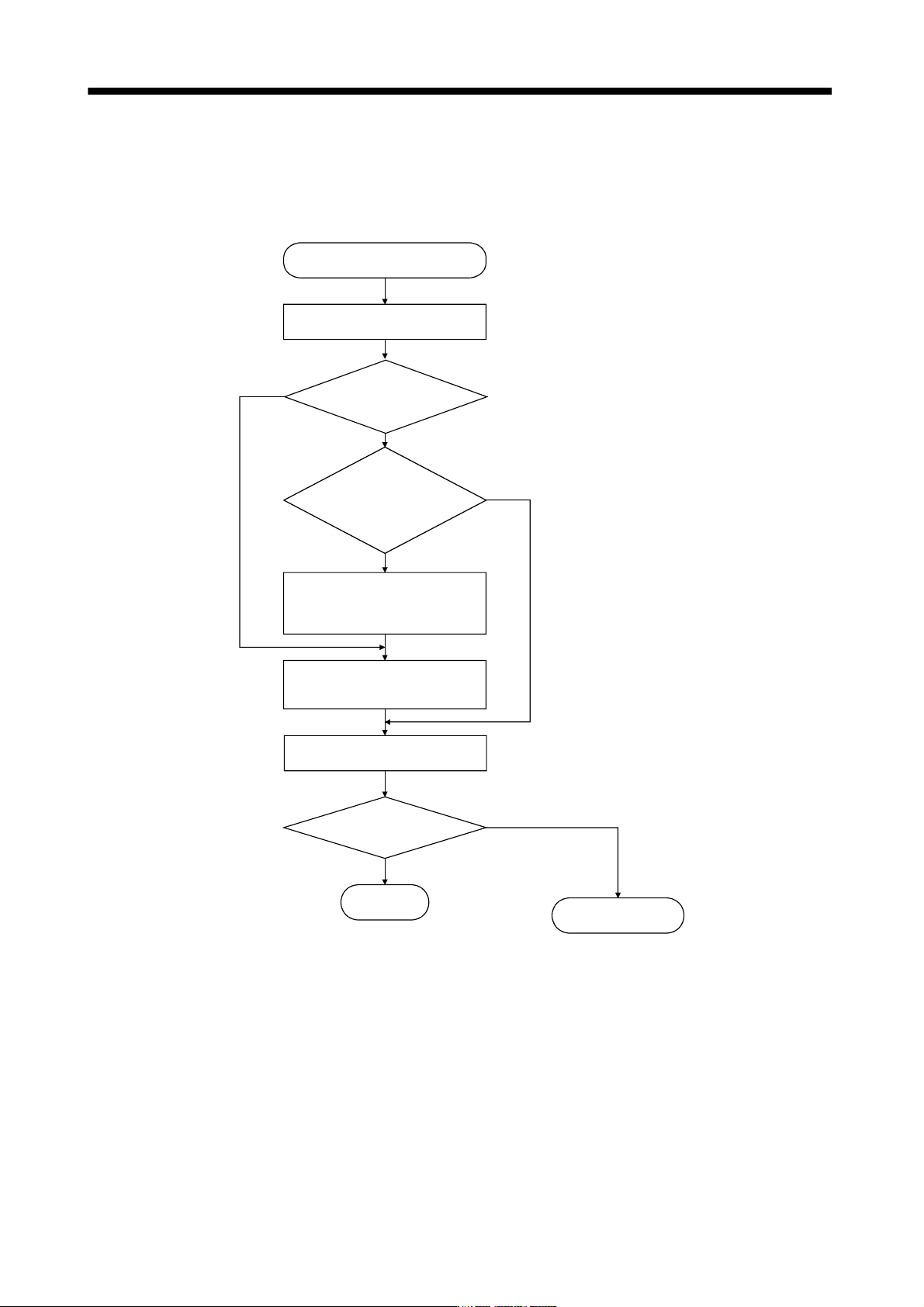
6.2.3 Adjustment procedure by auto tuning
Since auto tuning is made valid before shipment from the factory, simply running the servo motor automatically
sets the optimum gains that match the machine. Merely changing the response level setting value as required
completes the adjustment. The adjustment procedure is as follows.
END
Yes
No
Yes
No
No
Yes
Auto tuning adjustment
Acceleration/deceleration repeated
Load inertia moment ratio
estimation value stable?
Auto tuning
conditions not satisfied.
(Estimation of load inertia
moment ratio is difficult)
Adjust response level setting
so that desired response is
achieved on vibration-free level.
Acceleration/deceleration repeated
Requested
performance satisfied?
To manual mode
Choose the auto tuning mode 2
(parameter No.PA08 : 0002) and
set the load inertia moment ratio
(parameter No.PB06) manually.
6 - 6
6. GENERAL GAIN ADJUSTMENT
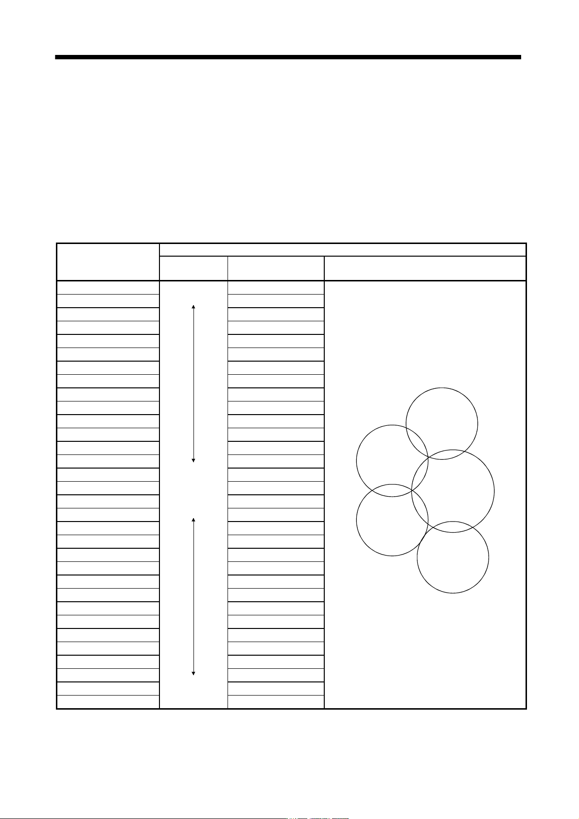
6.2.4 Response level setting in auto tuning mode
Set the response (The first digit of parameter No.PA09) of the whole servo system. As the response level
setting is increased, the track ability and settling time for a command decreases, but a too high response level
will generate vibration. Hence, make setting until desired response is obtained within the vibration-free range.
If the response level setting cannot be increased up to the desired response because of machine resonance
beyond 100Hz, filter tuning mode (parameter No.PB01) or machine resonance suppression filter (parameter
No.PB13 to PB16) may be used to suppress machine resonance. Suppressing machine resonance may allow
the response level setting to increase. Refer to section 7.3 for filter tuning mode and machine resonance
suppression filter.
Setting of parameter No.PA09
Response level setting
Machine characteristic
Machine rigidity
Machine resonance
frequency guideline
Guideline of corresponding machine
1 Low 10.0
Large conveyor
Arm robot
General machine
tool conveyor
Precision
working
machine
Inserter
Mounter
Bonder
2
11.3
3 12.7
4 14.3
5 16.1
6 18.1
7 20.4
8 23.0
9 25.9
10 29.2
11 32.9
12 37.0
13 41.7
14 47.0
15 52.9
16 Middle 59.6
17
67.1
18 75.6
19 85.2
20 95.9
21 108.0
22 121.7
23 137.1
24 154.4
25 173.9
26 195.9
27 220.6
28 248.5
29 279.9
30 315.3
31 355.1
32 High 400.0
6 - 7
6. GENERAL GAIN ADJUSTMENT
6.3 Manual mode 1 (simple manual adjustment)
If you are not satisfied with the adjustment of auto tuning, you can make simple manual adjustment with three
parameters.
POINT
If machine resonance occurs, filter tuning mode (parameter No.PB01) or
machine resonance suppression filter (parameter No.PB13 to PB16) may be
used to suppress machine resonance. (Refer to section 7.3.)
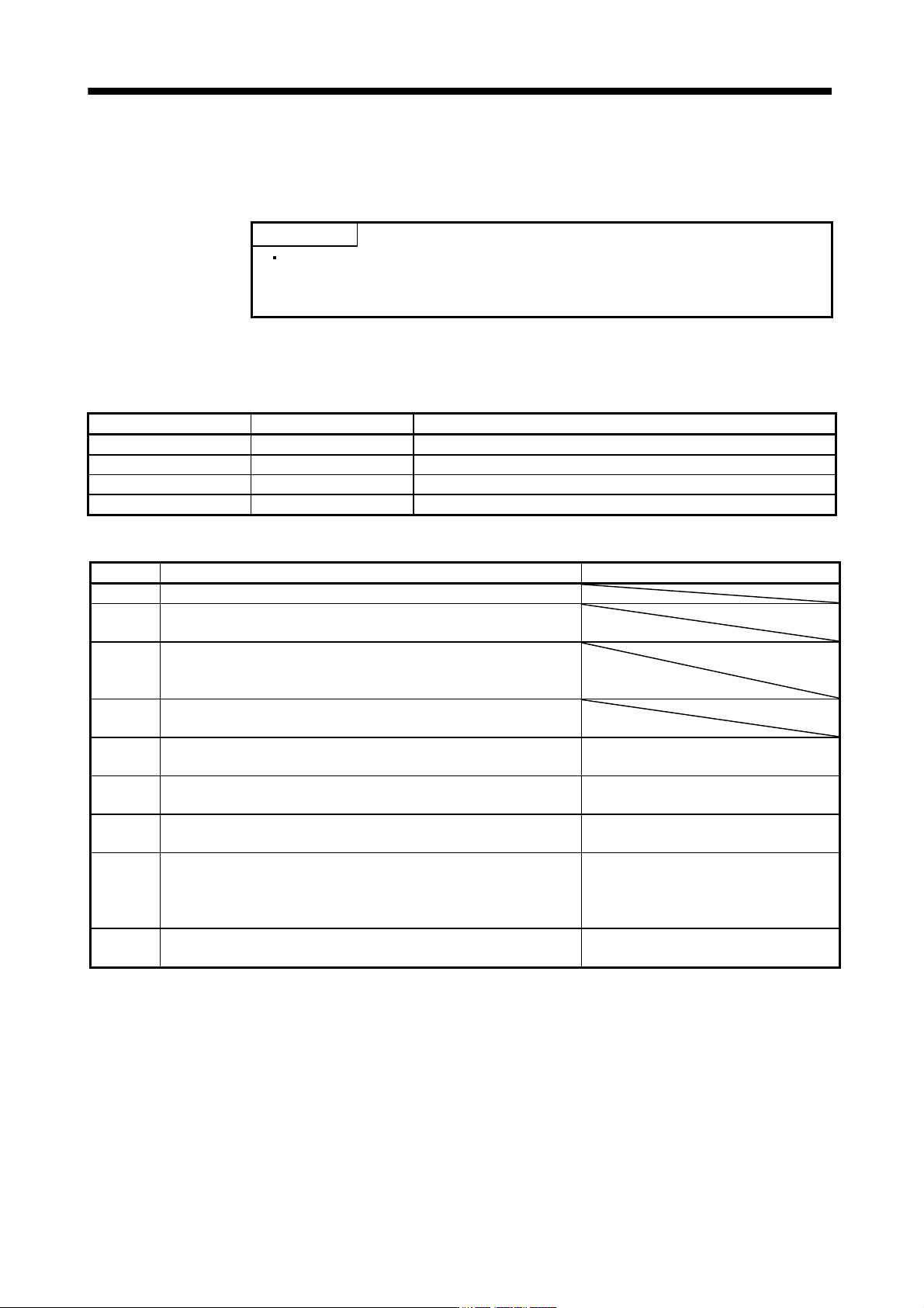
(1) For speed control
(a) Parameters
The following parameters are used for gain adjustment.
Parameter No. Abbreviation Name
PB06 GD2 Ratio of load inertia moment to servo motor inertia moment
PB07 PG1 Model loop gain
PB09 VG2 Speed loop gain
PB10 VIC Speed integral compensation
(b) Adjustment procedure
Step Operation Description
1 Brief-adjust with auto tuning. Refer to section 6.2.3.
2 Change the setting of auto tuning to the manual mode (Parameter
No.PA08: 0003).
3 Set an estimated value to the ratio of load inertia moment to servo motor
inertia moment. (If the estimate value with auto tuning is correct, setting
change is not required.)
4 Set a slightly smaller value to the model loop gain
Set a slightly larger value to the speed integral compensation.
5 Increase the speed loop gain within the vibration- and unusual noise-free
range, and return slightly if vibration takes place.
Increase the speed loop gain.
6 Decrease the speed integral compensation within the vibration-free range,
and return slightly if vibration takes place.
Decrease the time constant of the speed
integral compensation.
7 Increase the model loop gain, and return slightly if overshooting takes
place.
Increase the model loop gain.
8 If the gains cannot be increased due to mechanical system resonance or
the like and the desired response cannot be achieved, response may be
increased by suppressing resonance with filter tuning mode or machine
resonance suppression filter and then executing steps 2 and 3.
Suppression of machine resonance.
Refer to section 7.2, 7.3.
9 While checking the settling characteristic and rotational status, fine-adjust
each gain.
Fine adjustment