sh030051g.pdf - 第239页
11 - 34 11. OPTIONS AND AUXILI ARY EQUIPMENT 11.3 FR-BU2-(H) Brake unit POINT Use a 200V class brake unit and a resist or unit with a 200V class servo amplifier, and a 400V class brake unit and a re sistor unit with a 40…
11 - 33
11. OPTIONS AND AUXILIARY EQUIPMENT
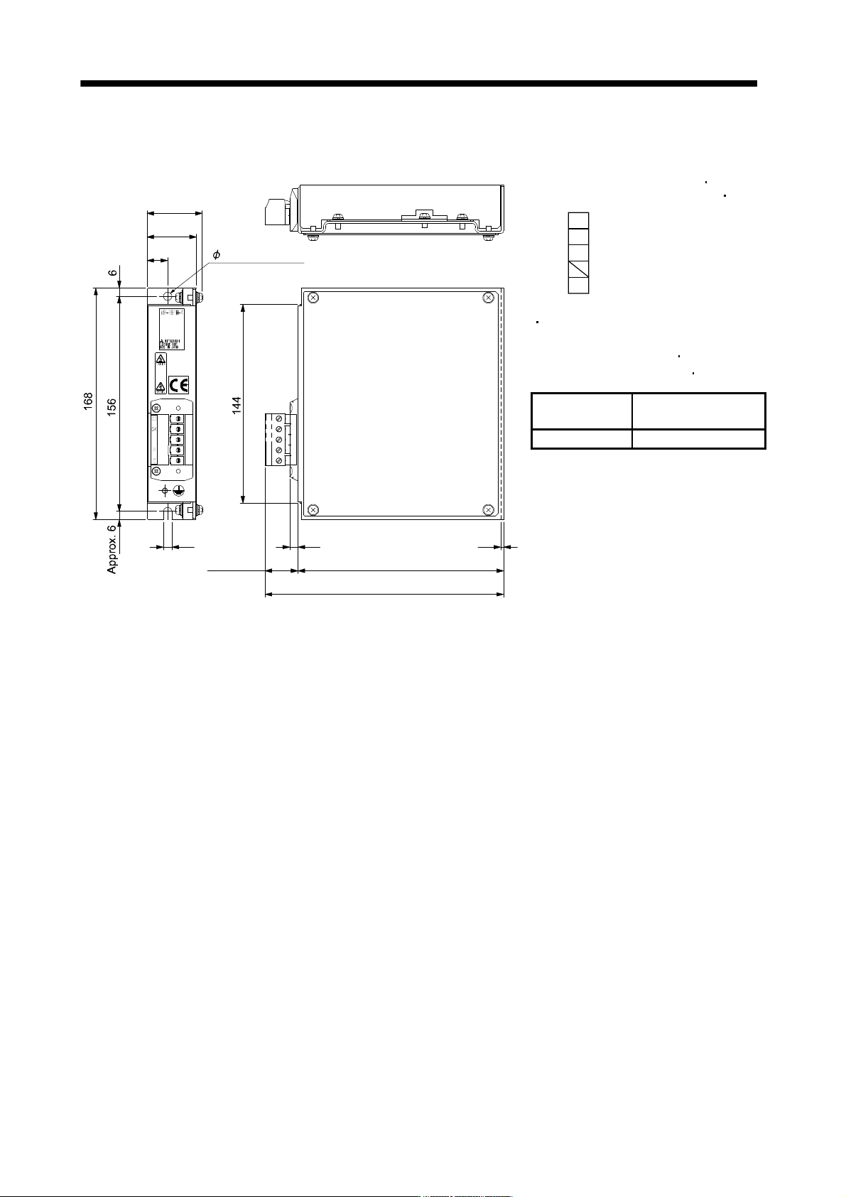
(f) MR-RB1H-4
[Unit: mm (in)]
TE1
6
2
149
173
6
Approx. 24
15
36
40
6 mounting hole
Terminal screw: M3
Tightening torque: 0.5 to 0.6 [N
m]
(4.43 to 5.31 [lb
in])
G3
G4
P
C
Mounting screw
Screw size: M5
Tightening torque: 3.24 [N
m]
(28.32 [lb
in])
Regenerative
option
Mass [kg] ([lb])
MR-RB1H-4 1.1 (2.4)

11 - 34
11. OPTIONS AND AUXILIARY EQUIPMENT
11.3 FR-BU2-(H) Brake unit
POINT
Use a 200V class brake unit and a resistor unit with a 200V class servo
amplifier, and a 400V class brake unit and a resistor unit with a 400V class
servo amplifier. Combination of different voltage class units and servo
amplifier cannot be used.
Install a brake unit and a resistor unit on a flat surface vertically. When the
unit is installed horizontally or diagonally, the heat dissipation effect
diminishes.
Temperature of the resistor unit case rises to higher than 100 . Keep cables
and flammable materials away from the case.
Ambient temperature condition of the brake unit is between 10 (14 ) and
50 (122 ). Note that the condition is different from the ambient
temperature condition of the servo amplifier (between 0
(32 ) and 55
(131
)).
Configure the circuit to shut down the power-supply with the alarm output of
the brake unit and resistor unit under abnormal condition.
Use the brake unit with a combination indicated in section 11.3.1.
For executing a continuous regenerative operation, use FR-RC-(H) power
regeneration converter or FR-CV-(H) power regeneration common converter.
Brake unit and regenerative options (Regenerative resistor) cannot be used
simultaneously.
Connect the brake unit to the bus of the servo amplifier. As compared to the MR-RB regenerative option, the
brake unit can return larger power. Use the brake unit when the regenerative option cannot provide sufficient
regenerative capability.
When using the brake unit, set the parameter No.PA02 of the servo amplifier to "
01".
When using the brake unit, always refer to the FR-BU2-(H) Brake Unit Instruction Manual.

11 - 35
11. OPTIONS AND AUXILIARY EQUIPMENT
11.3.1 Selection
Use a combination of servo amplifier, brake unit and resistor unit listed below.
Brake unit Resistor unit
Number of
connected
units
Permissible
continuous
power [kW]
Total
resistance
[
]
Applicable servo
amplifier
200V FR-BU2-15K FR-BR-15K 1 0.99 8 MR-J3-500B (Note)
class 2 (parallel) 1.98 4 MR-J3-500B
MR-J3-700B
MR-J3-11KB
MR-J3-15KB
FR-BU2-30K FR-BR-30K 1 1.99 4 MR-J3-500B
MR-J3-700B
MR-J3-11KB
MR-J3-15KB
FR-BU2-55K FR-BR-55K 1 3.91 2 MR-J3-11KB
MR-J3-15KB
MR-J3-22KB
MT-BR5-55K 1 5.5 2 MR-J3-22KB
400V
class
FR-BU2-H30K FR-BR-H30K 1 1.99 16 MR-J3-500B4
MR-J3-700B4
MR-J3-11KB4
FR-BU2-H55K FR-BR-H55K 1 3.91 8 MR-J3-11KB4
MR-J3-15KB4
MR-J3-22KB4
FR-BU2-H75K MT-BR5-H75K 1 7.5 6.5 MR-J3-22KB4
11.3.2 Brake unit parameter setting
Normally, when using the FR-BU2-(H), changing parameters is not necessary. Whether a parameter can be
changed or not is listed below.
Parameter
Change
possible/
impossible
Remarks
No. Name
0 Brake mode switchover Impossible Do not change the parameter.
1 Monitor display data selection Possible Refer to the FR-BU2-(H) Brake Unit
Instruction Manual.
2 Input terminal function selection 1 Impossible Do not change the parameter.
3 Input terminal function selection 2
77 Parameter write selection
78 Cumulative energization time
carrying-over times
CLr Parameter clear
ECL Alarm history clear
C1 For manufacturer setting