sh030051g.pdf - 第411页
App. - 8 A PPENDI X App. 5.4 OUTLINE DRAWINGS (Cha pter 9 OUTLINE DRAWINGS) [Unit: mm] Approx.14 Approx. 25.5 90 168 6 78 6 45 6 156 6 6 mounting h o le 195 21.4 Approx.80 Cooling fan wind direction Approx.68 6 85 With M…
App. - 7
A
PPENDI
X
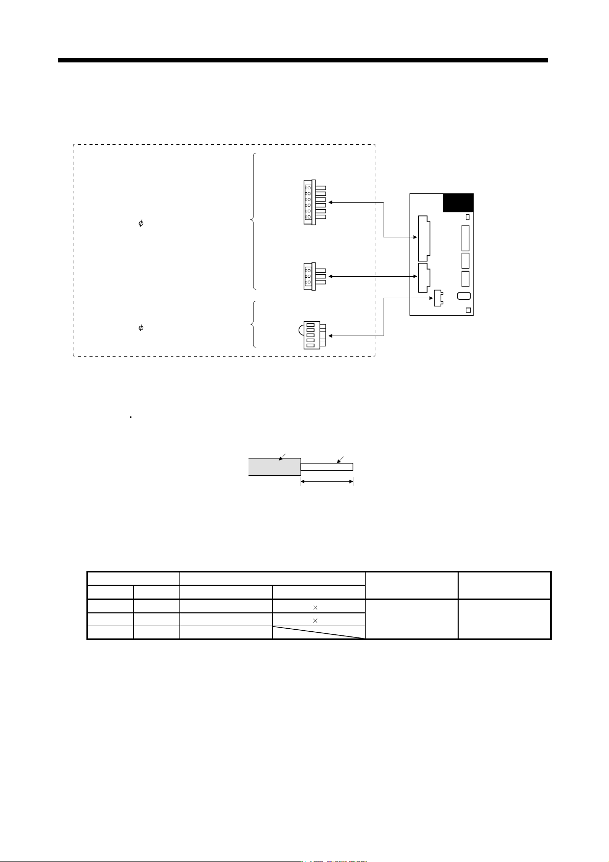
App. 5.3 CNP1, CNP2, CNP3 wiring method (3.3.3 CNP1, CNP2, CNP3 wiring method)
(a) Servo amplifier power supply connectors
Servo amplifier power supply connectors
CNP3
CNP1
CNP2
Connector for CNP1
PC4/6-STF-7.62-CRWH
(Phoenix Contact)
<Applicable cable example>
Cable finish OD: 5mm or less
Connector for CNP3
PC4/3-STF-7.62-CRWH
(Phoenix Contact)
Connector for CNP2(Note)
54928-0520 (Molex)
Servo amplifier
<Applicable cable example>
Cable finish OD: 3.8mm or less
Note. As twin type connector for CNP2 (L11, L21) is the same as MR-J3-100B or smaller. Refer to section (1) (c).
(b) Termination of the cables
1) CNP1
CNP3
Solid wire: After the sheath has been stripped, the cable can be used as it is.
7mm
Sheath
Core
Twisted wire: Use the cable after stripping the sheath and twisting the core. At this time, take care to
avoid a short caused by the loose wires of the core and the adjacent pole. Do not
solder the core as it may cause a contact fault. Alternatively, a bar terminal may be
used to put the wires together.
Cable size Bar terminal type
Crimping tool Manufacturer
[mm
2
] AWG For 1 cable For 2 cables
1.25/1.5 16 AI1.5-8BK AI-TWIN2 1.5-8BK
2.0/2.5 14 AI2.5-8BU AI-TWIN2 2.5-10BU CRIMPFOX-ZA3 Phoenix Contact
3.5 12 AI4-10Y
2) CNP2
CNP2 is the same as MR-J3-100B or smaller capacities. Refer to section 3.3.3 (1) (b).
App. - 8
A
PPENDI
X
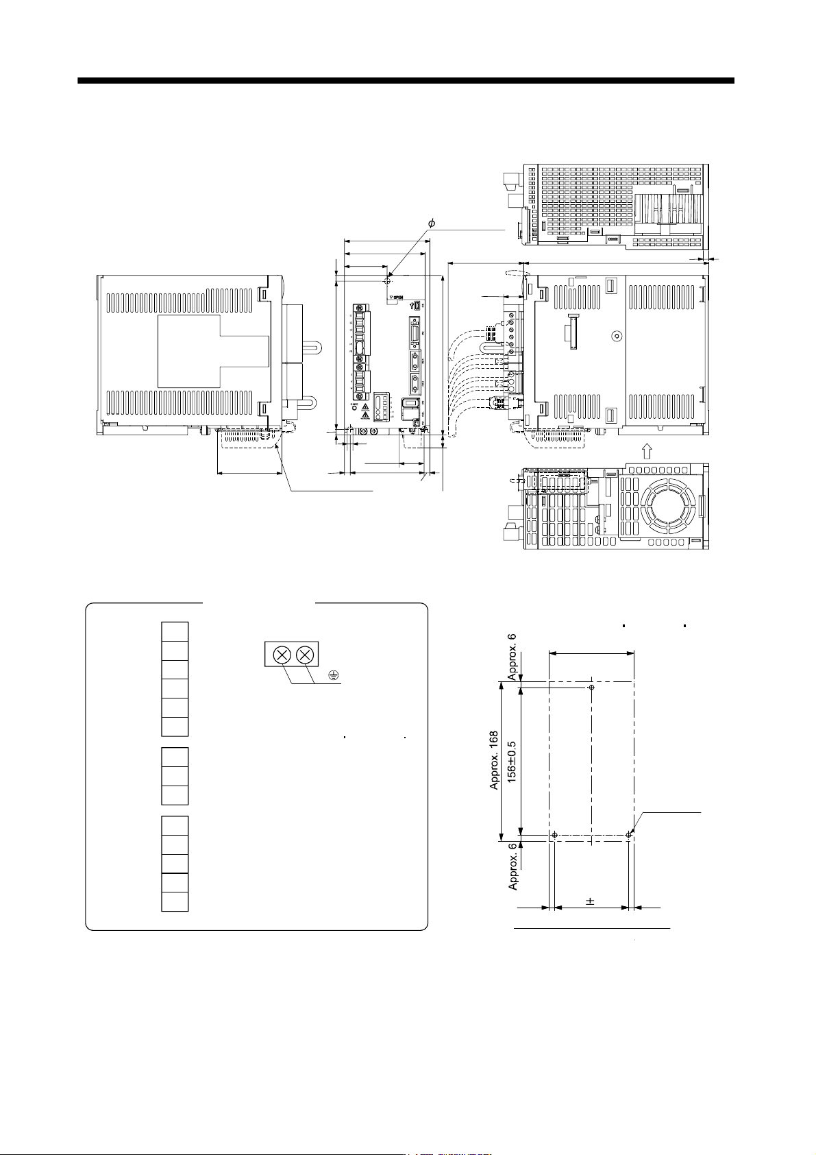
App. 5.4 OUTLINE DRAWINGS (Chapter 9 OUTLINE DRAWINGS)
[Unit: mm]
Approx.14
Approx.
25.5
90
168
6
78
6
45
6
156
6
6 mounting hole
195
21.4
Approx.80
Cooling fan
wind direction
Approx.68
6
85
With MR-J3BAT
6
Mass: 2.3 [kg] (5.07 [lb])
U
V
W
CNP3
P
C
D
L
11
L
21
CNP2
L1
L
2
L
3
N
P
1
P2
CNP1
Terminal signal layout
PE terminal
Screw size: M4
Tightening torque:
1.2 [N m] (10.6 [lb in])
Approx. 90
78 0.3
Approx. 6
Approx. 6
3-M5 screw
Mounting hole process drawing
Mounting screw
Screw size: M5
Tightening torque: 3.24 [N m] (28.7 [lb in])
App. - 9
A
PPENDI
X
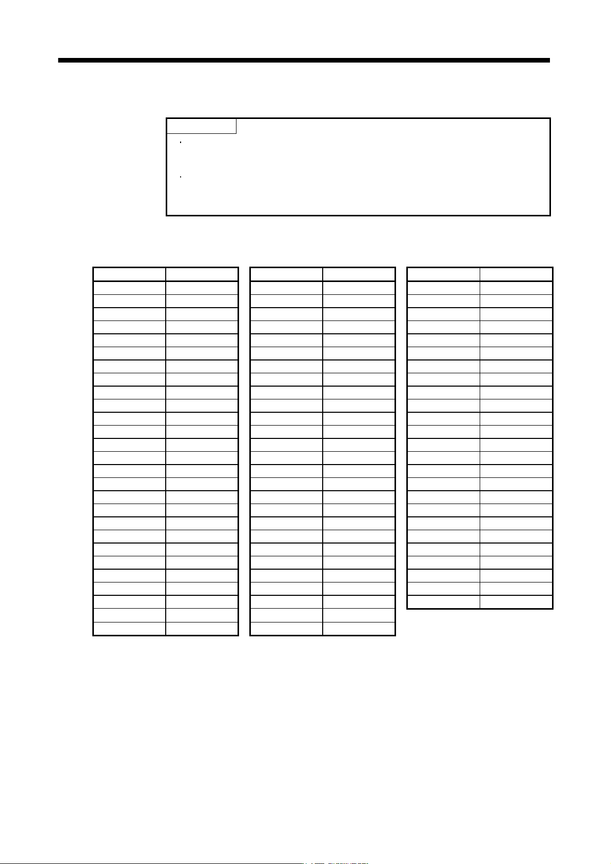
App. 6 Selection example of servo motor power cable
POINT
Selection condition of wire size is as follows.
Wire length: 30m or less
Depending on the cable selected, there may be cases that the cable does not
fit into the Mitsubishi optional or recommended cable clamp. Select a cable
clamp according to the cable diameter.
Selection example when using the 600V grade EP rubber insulated chloroprene sheath cab-tire cable (2PNCT)
for servo motor power (U, V, and W) is indicated below.
Servo motor Wire size [mm
2
] Servo motor Wire size [mm
2
] Servo motor Wire size [mm
2
]
HF-SP52 1.25 HC-LP152 2 HA-LP30K2 60
HF-SP102 1.25 HC-LP202 3.5 HA-LP37K2 60
HF-SP152 2 HC-LP302 5.5 HA-LP6014 5.5
HF-SP202 2 HC-UP72 1.25 HA-LP8014 5.5
HF-SP352 3.5 HC-UP152 2 HA-LP12K14 8
HF-SP502 5.5 HC-UP202 3.5 HA-LP15K14 14
HF-SP702 8 HC-UP352 5.5 HA-LP20K14 14
HF-SP51 1.25 HC-UP502 5.5 HA-LP25K14 22
HF-SP81 1.25 HA-LP601 8 HA-LP30K14 22
HF-SP121 2 HA-LP801 14 HA-LP37K14 22
HF-SP201 2 HA-LP12K1 14 HA-LP701M4 5.5
HF-SP301 3.5 HA-LP15K1 22 HA-LP11K1M4 8
HF-SP421 5.5 HA-LP20K1 38 HA-LP15K1M4 14
HF-SP524 1.25 HA-LP25K1 38 HA-LP22K1M4 14
HF-SP1024 1.25 HA-LP30K1 38 HA-LP30K1M4 22
HF-SP1524 2 HA-LP37K1 60 HA-LP37K1M4 22
HF-SP2024 2 HA-LP701M 8 HA-LP45K1M4 38
HF-SP3524 2 HA-LP11K1M 14 HA-LP50K1M4 38
HF-SP5024 3.5 HA-LP15K1M 22 HA-LP11K24 8
HF-SP7024 5.5 HA-LP22K1M 38 HA-LP15K24 14
HC-RP103 2 HA-LP30K1M 60 HA-LP22K24 14
HC-RP153 2 HA-LP37K1M 60 HA-LP30K24 22
HC-RP203 (Note) 3.5 HA-LP502 5.5 HA-LP37K24 22
HC-RP353 (Note) 5.5 HA-LP702 8 HA-LP45K24 38
HC-RP503 (Note) 5.5 HA-LP11K2 14 HA-LP55K24 38
HC-LP52 1.25 HA-LP15K2 22
HC-LP102 1.25 HA-LP22K2 22
Note. Use a composite cable and others when combining with wiring of the electromagnetic brake power in the same cable.