sh030051g.pdf - 第386页
13 - 85 13. SERVO AMPLIFIERS WI TH A LARGE CAPACITY ( 30k TO 55kW ) 13.9.7 Line noise filter (FR-BLF) POINT This section explains ho w to use the line noise filter unique to servo amplifiers with a large capacity. Other …
13 - 84
13. SERVO AMPLIFIERS WITH A LARGE CAPACITY
(
30k TO 55kW
)
13.9.5 No-fuse breakers, fuses, magnetic contactors.
Always use one no-fuse breakers and one magnetic contactor with one drive unit.
Converter unit Drive unit
No-fuse breaker Fuse
Magnetic
contactor
Power factor
improving DC
reactor is not used
Power factor
improving DC
reactor is used
Class
Current
[A]
Voltage
AC [V]
MR-J3-CR55K
MR-J3-DU30KB 400A frame 250A 225A frame 225A 450
250
S-N150
MR-J3-DU37KB 400A frame 300A 400A frame 300A 500 S-N180
MR-J3-DU30KB4 225A frame 150A 225A frame 125A
T
225
600
S-N95
MR-J3-CR55K4
MR-J3-DU37KB4 225A frame 175A 225A frame 150A 250 S-N125
MR-J3-DU45KB4 225A frame 225A 225A frame 175A 350 S-N150
MR-J3-DU55KB4 400A frame 250A 225A frame 225A 400 S-N180
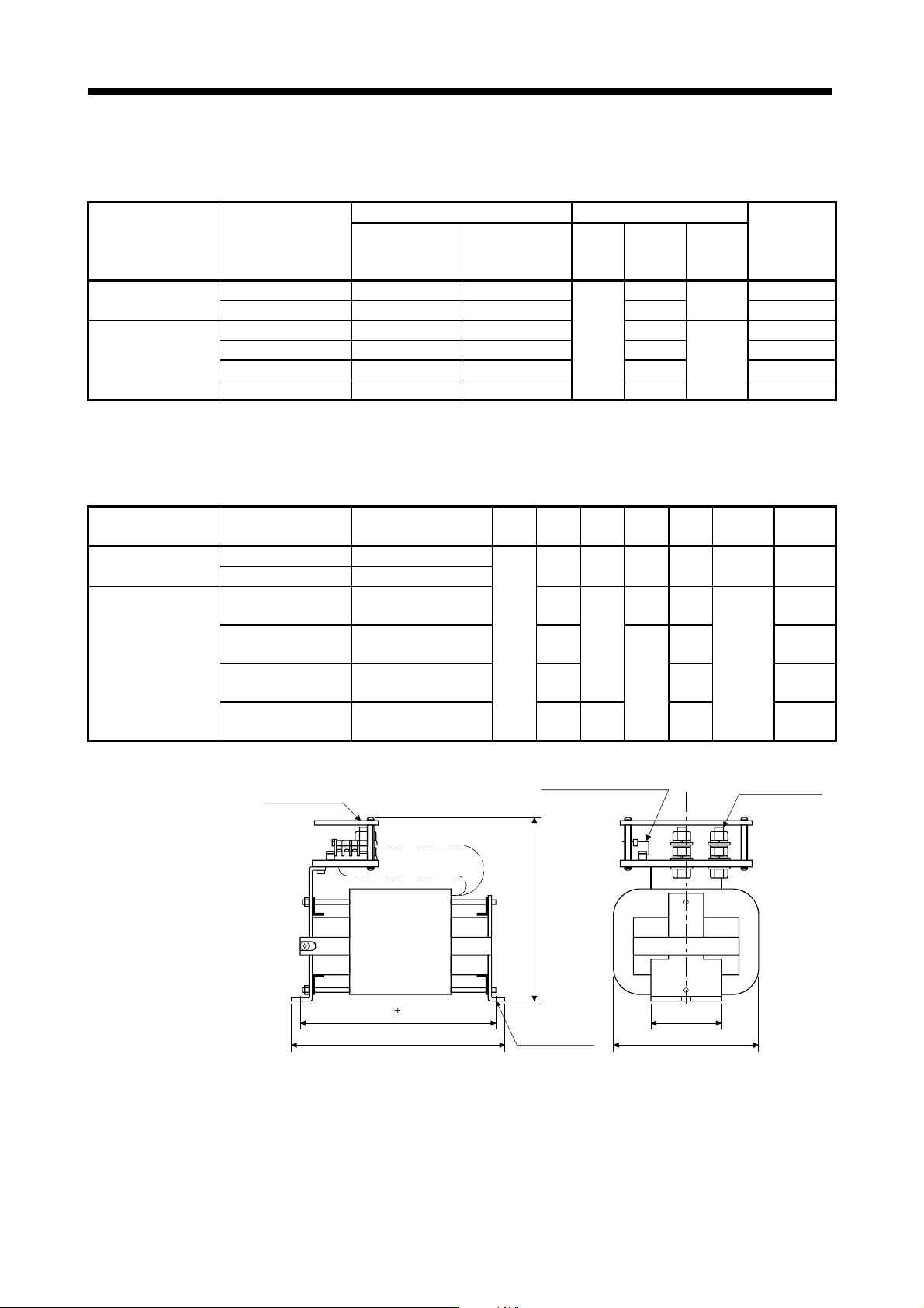
13.9.6 Power factor improving DC reactor
The input power factor is improved to about 95%.
[Unit: mm]
Converter unit Drive unit
Power factor improving
DC reactor
W D H W1 X
Terminal
screw
Mass
[kg (lb)]
MR-J3-CR55K
MR-J3-DU30KB MR-DCL30K
135
255 215 80 232 M12
9.5
(20.94)
MR-J3-DU37KB MR-DCL37K
MR-J3-DU30KB4 MR-DCL30K-4 205
200
75 175
M8
6.5
(14.33)
MR-J3-CR55K4
MR-J3-DU37KB4 MR-DCL37K-4 225
80
197
7
(15.43)
MR-J3-DU45KB4 MR-DCL45K-4 240 212
7.5
(16.54)
MR-J3-DU55KB4 MR-DCL55K-4 260 215 232
9.5
(20.94)
H or less
X
D or less
Terminal cover
Terminal screw
Terminal block (M3.5 screw)
For thermal sensor
P
1
P
2
Approx. W1
W or less
Mounting hole
for M8
1.5
1.5
13 - 85
13. SERVO AMPLIFIERS WITH A LARGE CAPACITY
(
30k TO 55kW
)
13.9.7 Line noise filter (FR-BLF)
POINT
This section explains how to use the line noise filter unique to servo amplifiers
with a large capacity. Other noise reduction products are the same as those
for servo amplifiers with 22kW or less. Refer to section 11.17.
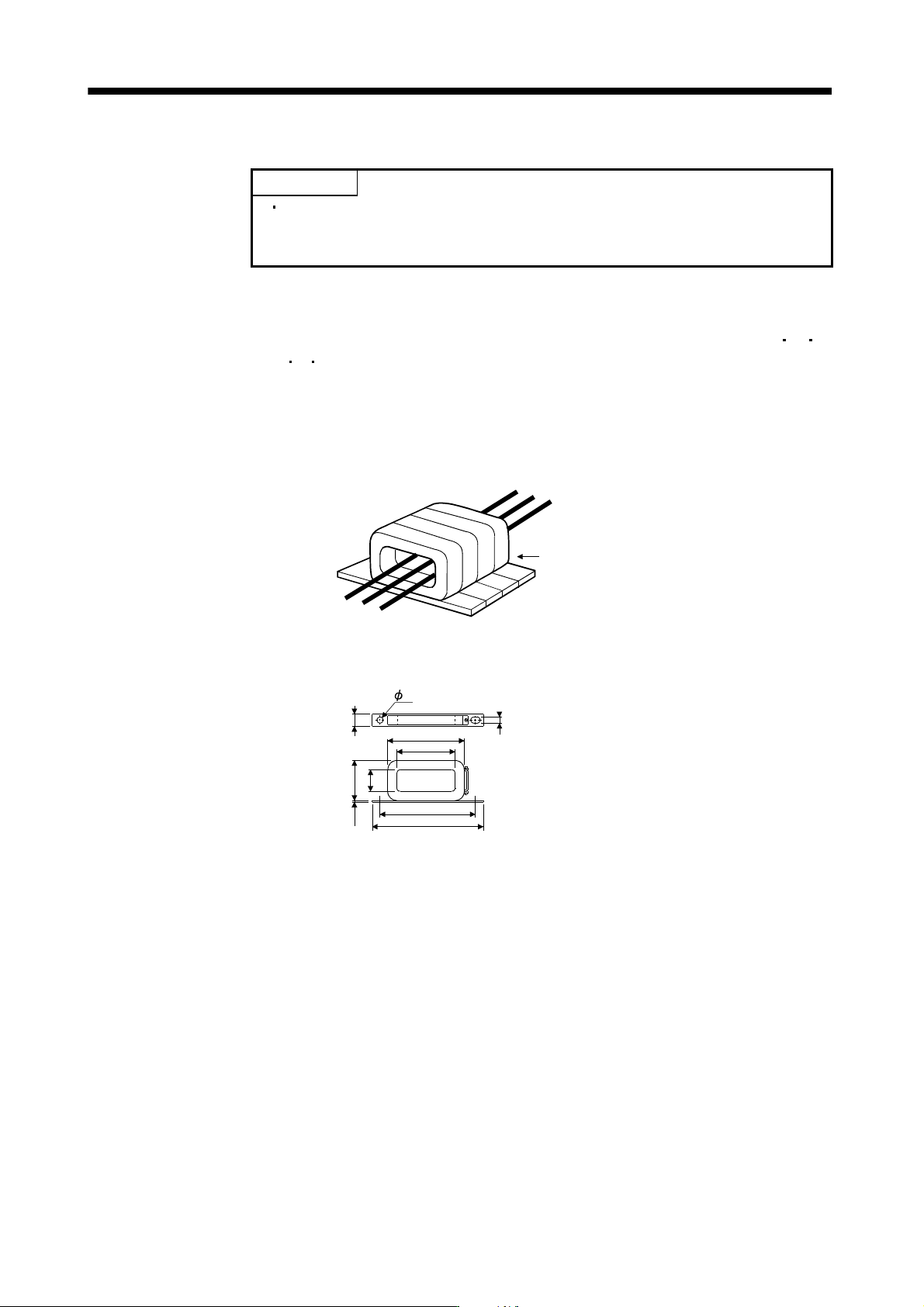
This filter is effective in suppressing noises radiated from the power supply side and output side of the
converter unit, drive unit and also in suppressing high-frequency leakage current (zero-phase current)
especially within 0.5MHz to 5MHz band. The filters are used with the converter power supply wires (L
1
L
2
L
3
)
and drive unit power wires (U
V W).
(1) Usage
Pass the 3-phase wires through four line noise filters. When using the line noise filters with the power wires,
passing the power wires together with the ground wire will reduce the filter effect. Run the ground wire
separately from the power wires.
Use four FR-BLFs.
(2) Outline drawing
[Unit: mm]
160
180
130
85
8
0
2
.
3
3
5
3
1
.
5
7
7
13 - 86
13. SERVO AMPLIFIERS WITH A LARGE CAPACITY
(
30k TO 55kW
)
13.9.8 Leakage current breaker
(1) Selection method
High-frequency chopper currents controlled by pulse width modulation flow in the AC servo circuits.
Leakage currents containing harmonic contents are larger than those of the motor which is run with a
commercial power supply.
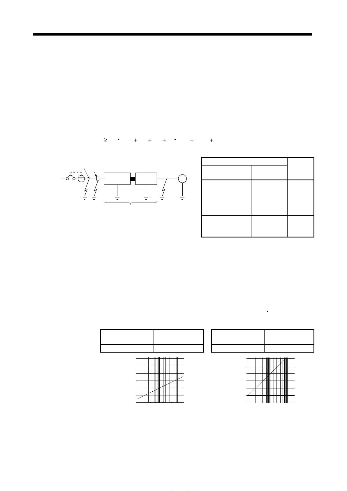
Select a leakage current breaker according to the following formula, and ground the drive unit, servo motor,
etc. securely.
Make the input and output cables as short as possible, and also make the grounding cable as long as
possible (about 30cm) to minimize leakage currents.
Rated sensitivity current
10 {Ig1 Ign Iga K (Ig2 Igm)} [mA] ···································· (13.2)
K: Constant considering the harmonic contents
Ign
Noise filter
Cable
Ig1
NV
Converter
unit
Drive
unit
Cable
Iga
Ig2 Igm
M
Leakage current breaker
K
Type
Mitsubishi
products
Models provided with
harmonic and surge
reduction techniques
NV-SP
NV-SW
NV-CP
NV-CW
NV-HW
1
General models
BV-C1
NFB
NV-L
3
Ig1: Leakage current on the electric channel from the leakage current breaker to the input terminals of the drive
unit (Found from Fig. 13.3.)
Ig2: Leakage current on the electric channel from the output terminals of the servo amplifier to the servo
motor (Found from Fig. 13.3.)
Ign: Leakage current when a filter is connected to the input side (4.4mA per one FR-BIF or FR-BIF-H)
Iga: Leakage current of the drive unit (Found from Table 13.7.)
Igm: Leakage current of the servo motor (Found from Table 13.6.)
Table 13.6 Servo motor’s leakage current
example (lgm)
Table 13.7 Converter unit
drive unit's leakage
current Example (Iga)
Servo motor power
[kW]
Leakage current
[mA]
Converter unit
Drive unit
Leakage current
[mA]
30 to 55 2.5 All series 5
120
100
80
60
40
20
0
2
3.5
5.5
8
14
22
38
80
150
30
60
100
Leakage current [mA]
Cable size [mm
2
]
120
100
80
60
40
20
0
2
3.5
5.5
8
14
22
38
80
150
30
60
100
Leakage current [mA]
Cable size [mm
2
]
a) 200V class b) 400V class
Fig.13.3 Leakage current example (lg1, lg2) for CV cable run in metal conduit