sh030051g.pdf - 第61页
3 - 6 3. SIGNALS AND WI RING (5) MR-J3-500B MR-J3-700B EM1 NFB MC L 1 L 2 L 3 ALM RA1 P 1 DICOM DOCOM N U V W (Note 2) (Note 1) TE1 PE U V W 2 3 4 1 M Motor Encoder CN2 24VDC (Note 3 ) Encoder ca ble (Note 6) DOCOM Force…
3 - 5
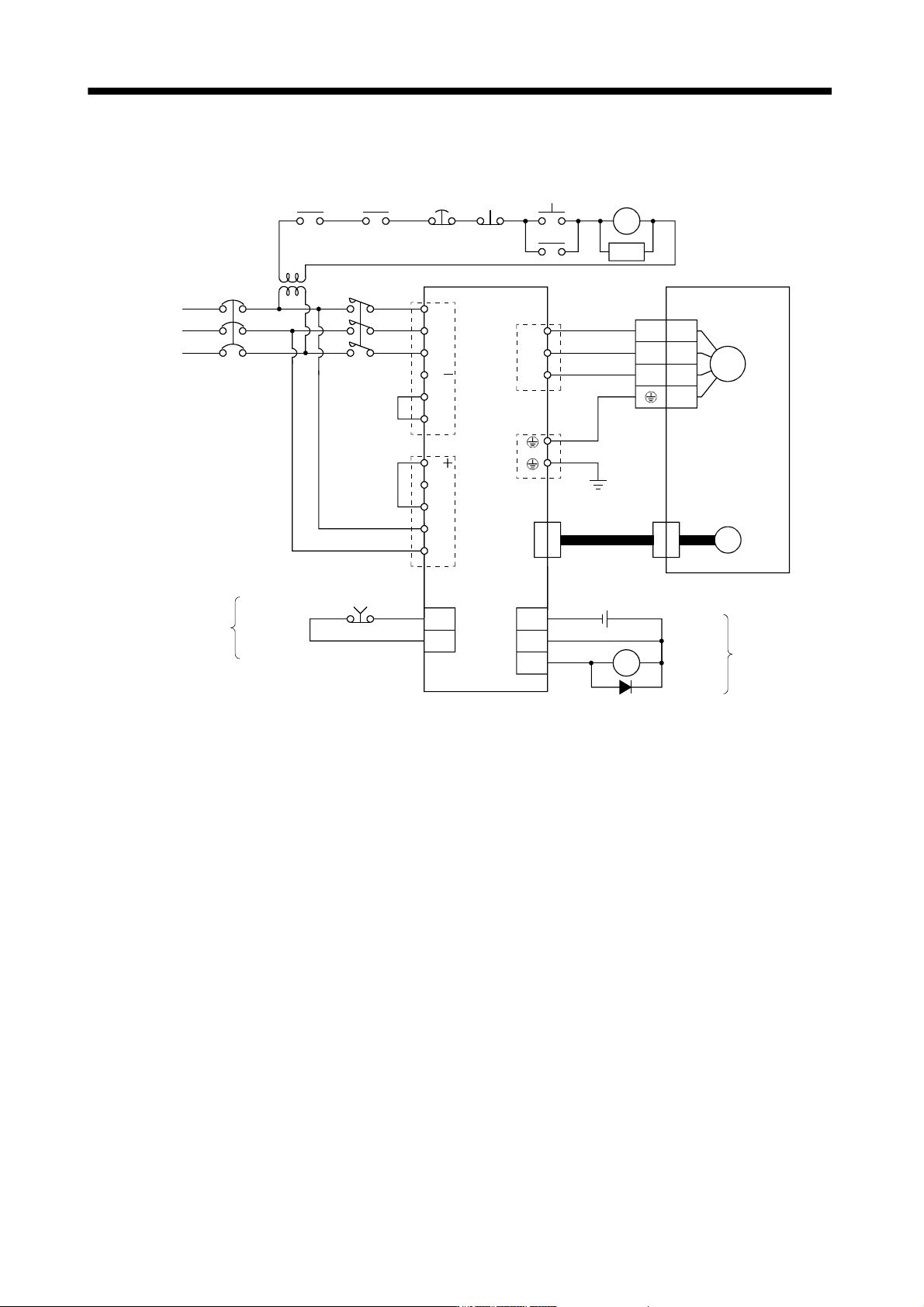
3. SIGNALS AND WIRING
(4) MR-J3-60B4 to MR-J3-200B4
EM1
NFB MC
L
1
L2
L
3
3-phase
200 to
230VAC
ALM RA1
P
1
P
DICOM
DOCOM
L
11
L21
N
D
C
U
V
W
(Note 1)
(Note 2)
CNP1
CNP3
PE
CNP2
U
V
W
2
3
4
1
M
Motor
Encoder
CN2
24VDC
(Note 3)
Encoder cable
(Note 6)
DOCOM
Forced stop
CN3CN3
OFF
Forced
stop
ON
MC
MC
SK
(Note 4)
Alarm
RA1
Controller
forced stop
RA2
Servo amplifier Servo motor
(Note 5)
Trouble
(Note 4)
(Note 5)
(Note 7)
Stepdown
transformer
P
2
Note 1. Always connect P1 and P2. (Factory-wired.) When using the power factor improving DC reactor, refer to section 11.13.
2. Always connect P and D. (Factory-wired.) When using the regenerative option, refer to section 11.2.
3. For the encoder cable, use of the option cable is recommended. Refer to section 11.1 for selection of the cable.
4. If deactivating output of trouble (ALM) with parameter change, configure up the power supply circuit which switches off the
magnetic contactor after detection of alarm occurrence on the controller side.
5. For the sink I/O interface. For the source I/O interface, refer to section 3.7.3.
6. Refer to section 3.10.
7. Stepdown transformer is required for coil voltage of magnetic contactor more than 200V class.
3 - 6
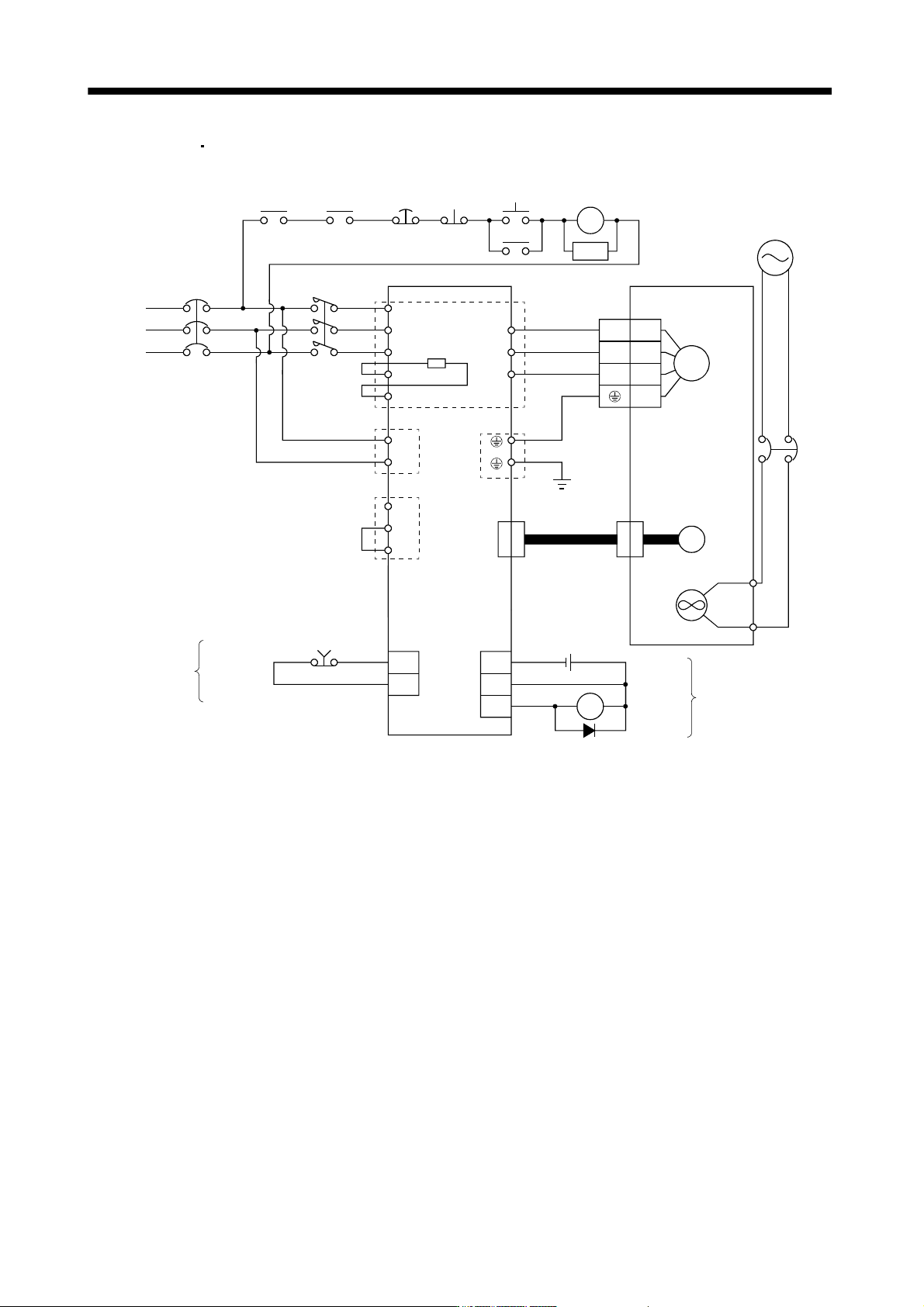
3. SIGNALS AND WIRING
(5) MR-J3-500B
MR-J3-700B
EM1
NFB MC
L
1
L
2
L
3
ALM RA1
P1
DICOM
DOCOM
N
U
V
W
(Note 2)
(Note 1)
TE1
PE
U
V
W
2
3
4
1
M
Motor
Encoder
CN2
24VDC
(Note 3)
Encoder cable
(Note 6)
DOCOM
Forced stop
CN3CN3
OFF
Forced
stop
ON
MC
MC
SK
(Note 4)
Alarm
RA1
Controller
forced stop
RA2
Servo amplifier Servo motor
(Note 5)
Trouble
(Note 4)
(Note 5)
3-phase
200 to
230VAC
L
11
L
21
TE2
P
1
P2
N
TE3
Built-in
regenerative
resistor
Cooling fan
(Note 7)
Power supply
of Cooling fan
BU
BV
NFB
Note 1. Always connect P1 and P2. (Factory-wired.) When using the power factor improving DC reactor, refer to section 11.13.
2. When using the regenerative option, refer to section 11.2.
3. For the encoder cable, use of the option cable is recommended. Refer to section 11.1 for selection of the cable.
4. If deactivating output of trouble (ALM) with parameter change, configure up the power supply circuit which switches off the
magnetic contactor after detection of alarm occurrence on the controller side.
5. For the sink I/O interface. For the source I/O interface, refer to section 3.7.3.
6. Refer to section 3.10.
7. A cooling fan is attached to the HA-LP601 and the HA-LP701M servo motors. For power supply specification of the cooling fan,
refer to section 3.10.2 (3) (b).
3 - 7
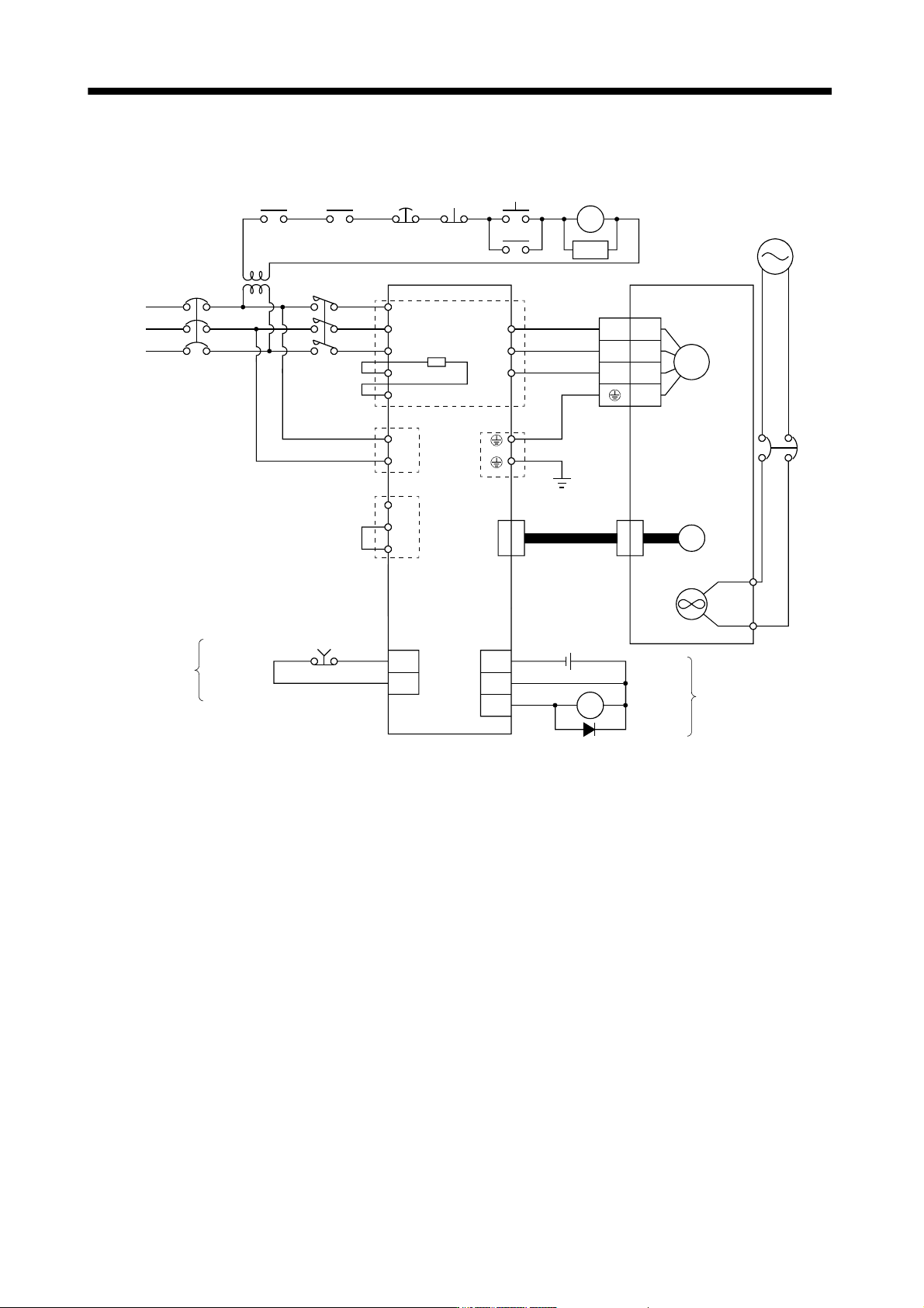
3. SIGNALS AND WIRING
(6) MR-J3-350B4 to MR-J3-700B4
EM1
NFB MC
L
1
L2
L
3
ALM RA1
C
DICOM
DOCOM
P
U
V
W
(Note 2)
(Note 1)
TE1
PE
U
V
W
2
3
4
1
M
Motor
Encoder
CN2
24VDC
(Note 3)
Encoder cable
(Note 6)
DOCOM
Forced stop
CN3CN3
OFF
Forced
stop
ON
MC
MC
SK
(Note 4)
Alarm
RA1
Controller
forced stop
RA2
Servo amplifier Servo motor
(Note 5)
Trouble
(Note 4)
(Note 5)
3-phase
380 to
480VAC
L11
L
21
TE2
P
1
P2
N
TE3
Built-in
regenerative
resistor
(Note 7)
Stepdown
transformer
Cooling fan
(Note 8)
Power supply
of Cooling fan
BU
BV
NFB
Note 1. Always connect P1 and P2. (Factory-wired.) When using the power factor improving DC reactor, refer to section 11.13.
2. When using the regenerative option, refer to section 11.2.
3. For the encoder cable, use of the option cable is recommended. Refer to section 11.1 for selection of the cable.
4. If deactivating output of trouble (ALM) with parameter change, configure up the power supply circuit which switches off the
magnetic contactor after detection of alarm occurrence on the controller side.
5. For the sink I/O interface. For the source I/O interface, refer to section 3.7.3.
6. Refer to section 3.10.
7. Stepdown transformer is required for coil voltage of magnetic contactor more than 200V class.
8. A cooling fan is attached to the HA-LP6014 and the HA-LP701M4 servo motors. For power supply specification of the cooling
fan, refer to section 3.10.2 (3) (b).