sh030051g.pdf - 第334页
13 - 33 13. SERVO AMPLIFIERS WI TH A LARGE CAPACITY ( 30k TO 55kW ) 13.3.5 Connectors and signal arran gements POINT The pin configurations of the conne cto rs are as viewed from the cable connector wiring se ction. (1) …
13 - 32
13. SERVO AMPLIFIERS WITH A LARGE CAPACITY
(
30k TO 55kW
)
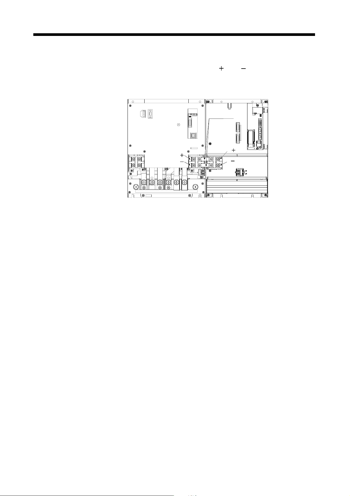
13.3.4 How to use the connection bars
Make sure to use the supplied connection conductors and connect the L
and L of the drive unit to those of
the converter unit as shown below. Never use connection conductors other than the ones supplied with the
drive unit. Both units are shown without the front covers.
L
L
L
L
Connection
conductors
Drive unitConverter unit
13 - 33
13. SERVO AMPLIFIERS WITH A LARGE CAPACITY
(
30k TO 55kW
)
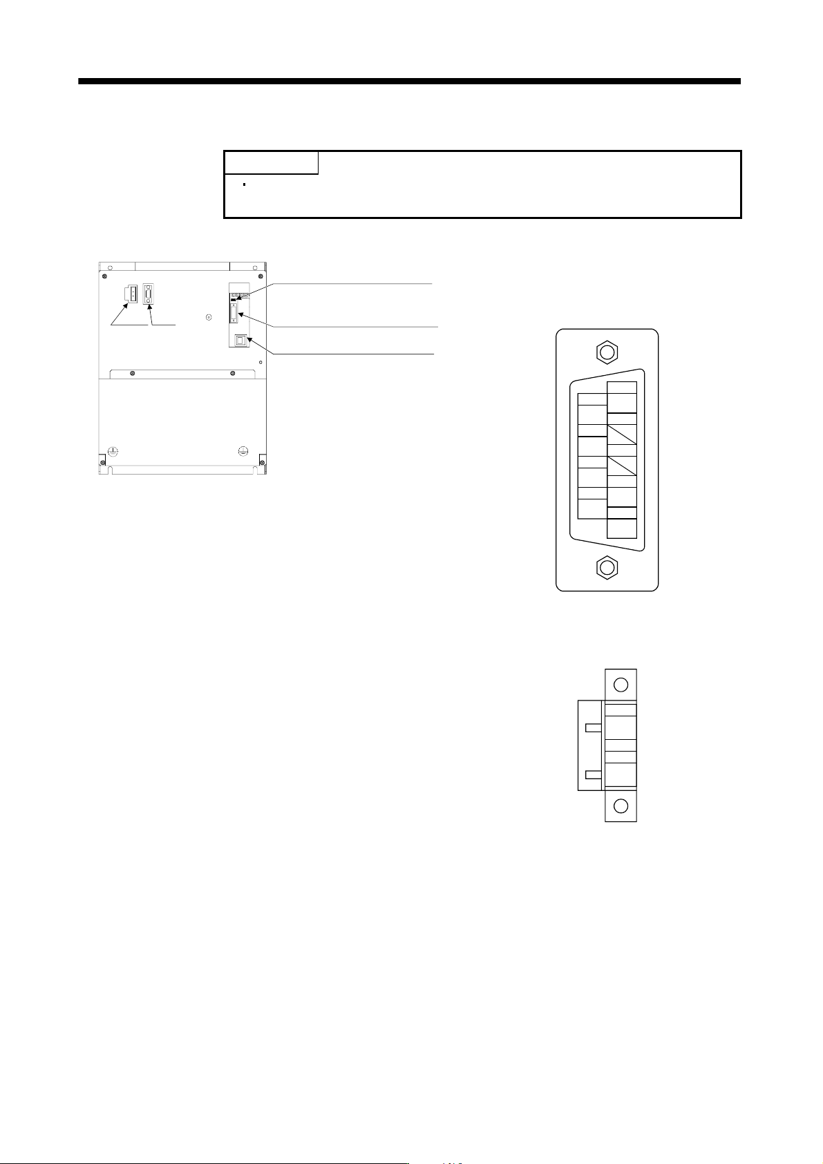
13.3.5 Connectors and signal arrangements
POINT
The pin configurations of the connectors are as viewed from the cable
connector wiring section.
(1) Converter unit
CN6 Leave this open.
CN40 Connect to CN40A of the
drive unit.
CN3 Leave this open.
CHARGE
CNP1 CN1
CN1 (Digital I/O connector)
Model: 17JE-23090-02 (D8A) K11-CG (D-sub 9 pin or
equivalent)
(DDK)
DICOM
WNG
9
DOCOM
5
2
4
6
7
3
1
8
DOCOM
EM1
DICOM
ALM
CNP1 (Magnetic contactor wiring connector)
Model: GFKC 2.5/2-STF-7.62
(Phoenix Contact)
1
MC1
2
MC2
13 - 34
13. SERVO AMPLIFIERS WITH A LARGE CAPACITY
(
30k TO 55kW
)
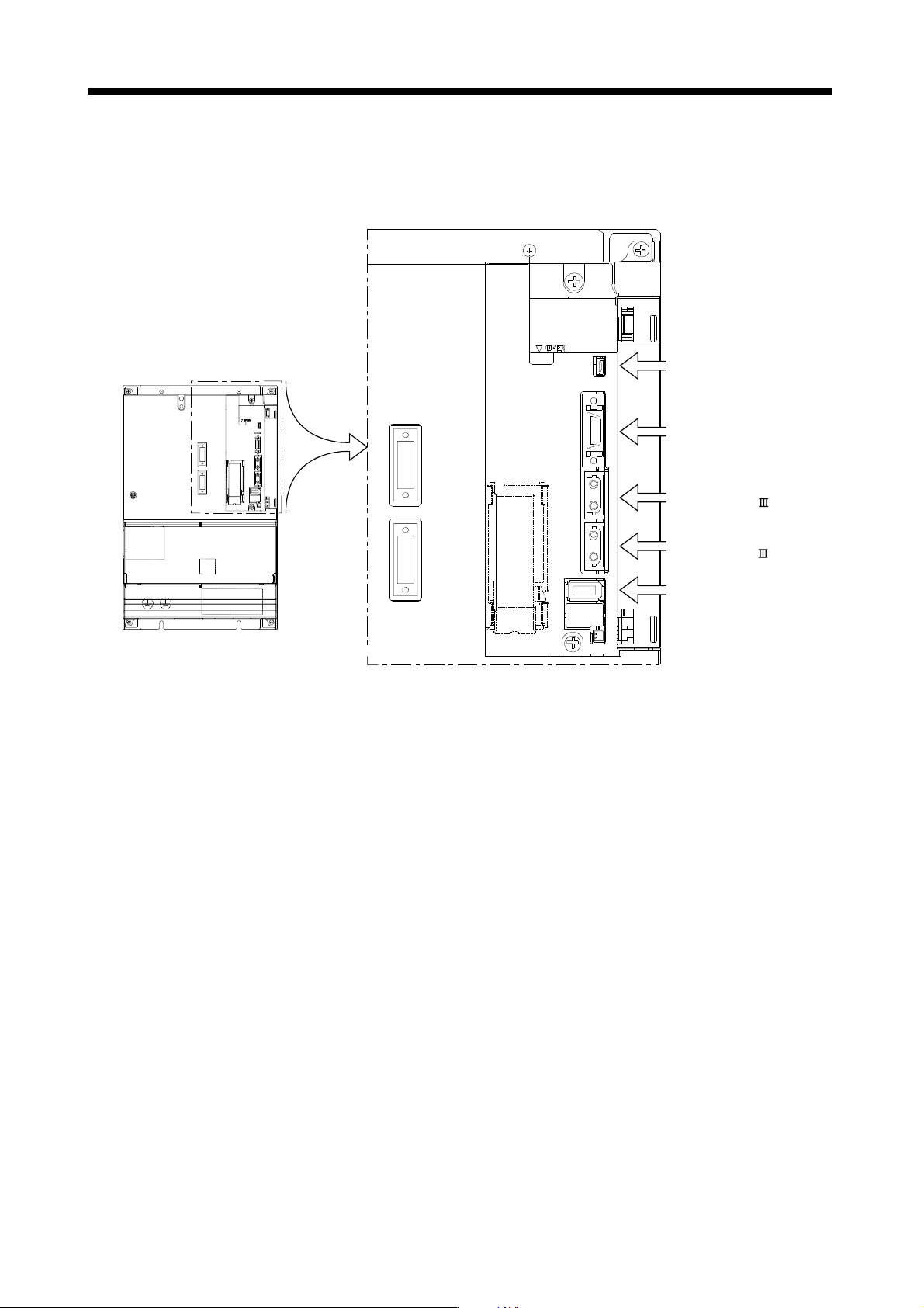
(2) Drive unit
The drive unit front view shown is that of the MR-J3-DU30KB4, MR-J3-DU37KB4 or less. Refer to section
13.7 Outline Drawings for the appearances and connector layouts of the MR-J3-DU30KB, MR-J3-DU37KB,
MR-J3-DU45KB4, MR-J3-DU55KB4.
The frames of the CN2 and CN3 connectors are
connected to the PE (earth) terminal in the amplifier.
Connector for the front axis of
CN1A SSCNET cable.
Connector for the rear axis of
CN1B SSCNET cable.
CN3 (I/O signal connector)
Refer to section 3.4.
CN5 (USB connector)
Refer to section 11.8.
CN2 (Encoder connector)
Refer to section 3.4.