SM482PLUS_Admin(Eng_Ver2.8).pdf - 第122页
6-4 Multi-Functional Placer SM482( L) PLUS Administrator’s Guide After teaching the two points, press “Ent er” to complete the initial theta teaching operation. <5. Place Origin> group Set the placement origin of…
6-3
Board Definition
Memo When performing compensation, the following conditions must be
satisfied simultaneously;
The PCB shall be transferred to the workstation of the conveyor.
The user mode shall not be ‘operator’.
More than two fiducial marks shall be set on the PCB.
<Initial Theta - Teach> button
This Button is used to teach the initial theta of PCB. When this Button is clicked
on, the following screens are displayed in succession.
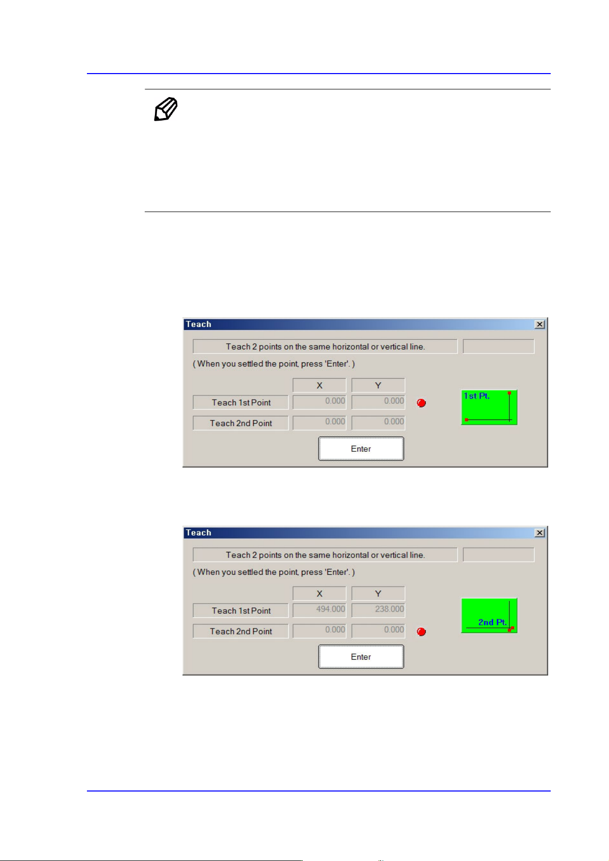
Teaching two points, which are in parallel horizontally or vertically on the PCB,
will calculate the initial angle of the PCB to compensate the PCB offset angle.
Teach the first point of the two points on the same horizontal line or vertical line
on the PCB. When the “Enter” key is pressed after teaching, the following screen
is displayed.
Teach the second point of two points on the same horizontal or vertical line on the
PCB. When the “Enter” key is pressed after teaching, the following screen is
displayed.
6-4
Multi-Functional Placer SM482(L) PLUS Administrator’s Guide
After teaching the two points, press “Enter” to complete the initial theta teaching
operation.
<5. Place Origin> group
Set the placement origin of the PCB. This origin is defined by the offset from the PCB
origin of the system to the placement origin of the PCB board. Set the fiducial point of
the board to be worked on based on the set coordinates.
Generally, perform setup by designating the pattern near the stopper. Designate a
position in the PCB which can be checked easily.
[Case 1 - Using the Board Stop]
It is difficult to apply to the array PCB
since it is not easy to check the
coordinate.
[Case 2 - Utilizing a pattern in the
PCB]
Utilize the pattern in the PCB and
apply it to the array PCB since it is
easy to check the coordinate.
6-5
Board Definition
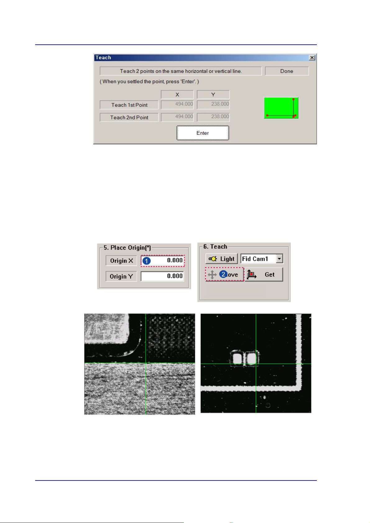
<Origin X> edit box
Set the X value of the placement origin of PCB.
<Origin Y> edit box
Set the Y value of the placement origin of PCB. Click on <Origin X> or <Origin
Y>, then click on the “Move” or “'Get” Button in the <8. Teach> group, Teaching
of placement origin is possible based on the selected object from the Combo Box.
<6. Teach> group
Used for moving the selected object from the Combo Box to the position of assigned
coordinates, or for obtaining the present coordinates by rotating the XY, Z axis driving
motor.
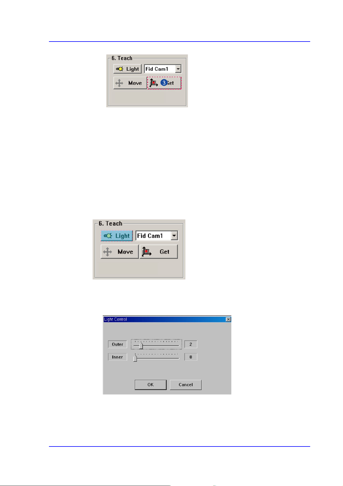
<Light> button
Sets the lighting for the fiducial camera. When this Button is clicked on, the
following dialog box is displayed.
Combo Box
Used for selecting the object to move to the designated coordinates by rotating the
XY, Z axis driving motor or to select the object for which the present coordinates
is searching. Selectable objects are as follows;