SM482PLUS_Admin(Eng_Ver2.8).pdf - 第449页
14-77 Machine Calibration time, At this time select the ‘Fly Cam1‘ in the <T arget Camera> combo box and click the <Light…> button and ad just the brightne ss of the light in the ‘Light Control’ dialog box so…
14-76
Multi-Functional Placer SM482(L) PLUS Administrator’s Guide
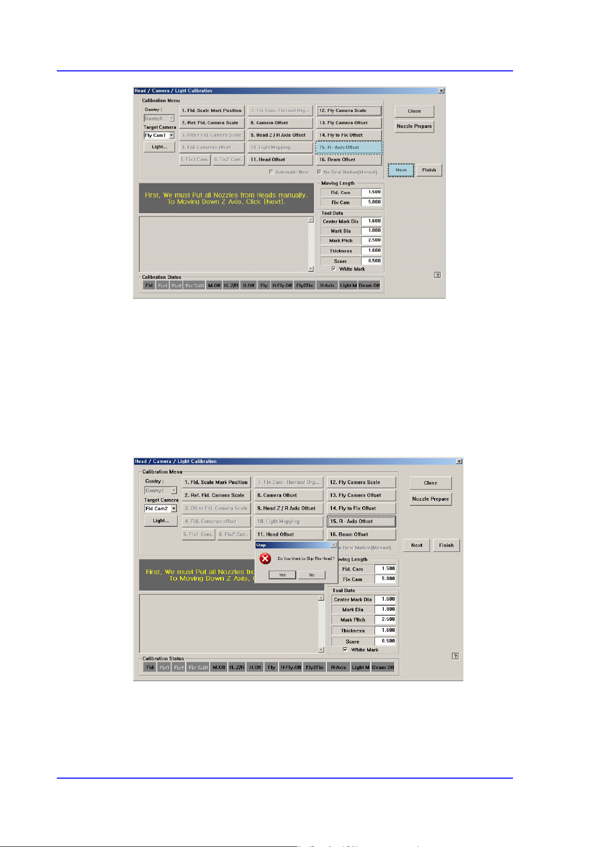
3. Then, after the head assembly moves to the home position on the machine, move all Z
axes down. At this time, remove all inserted nozzles manually.
4. Then the message “Next Attach the Calibration Tool to Head 1. Click [Next] for
Moving Down Head. After Moving, Attach the Tool to Head Manually” appears.
Click the <Next> button after inserting the CNT20 nozzle in the nozzle-holder of
Head #1 manually.
5. The message “Z Axis moving down…. Please Wait for a Moment.” appears, and the
dialog box asking whether to skip the calibration of Head1 is displayed. Click “Yes” to
skip or click “No” to proceed with the calibration. And then click the <Next> button.
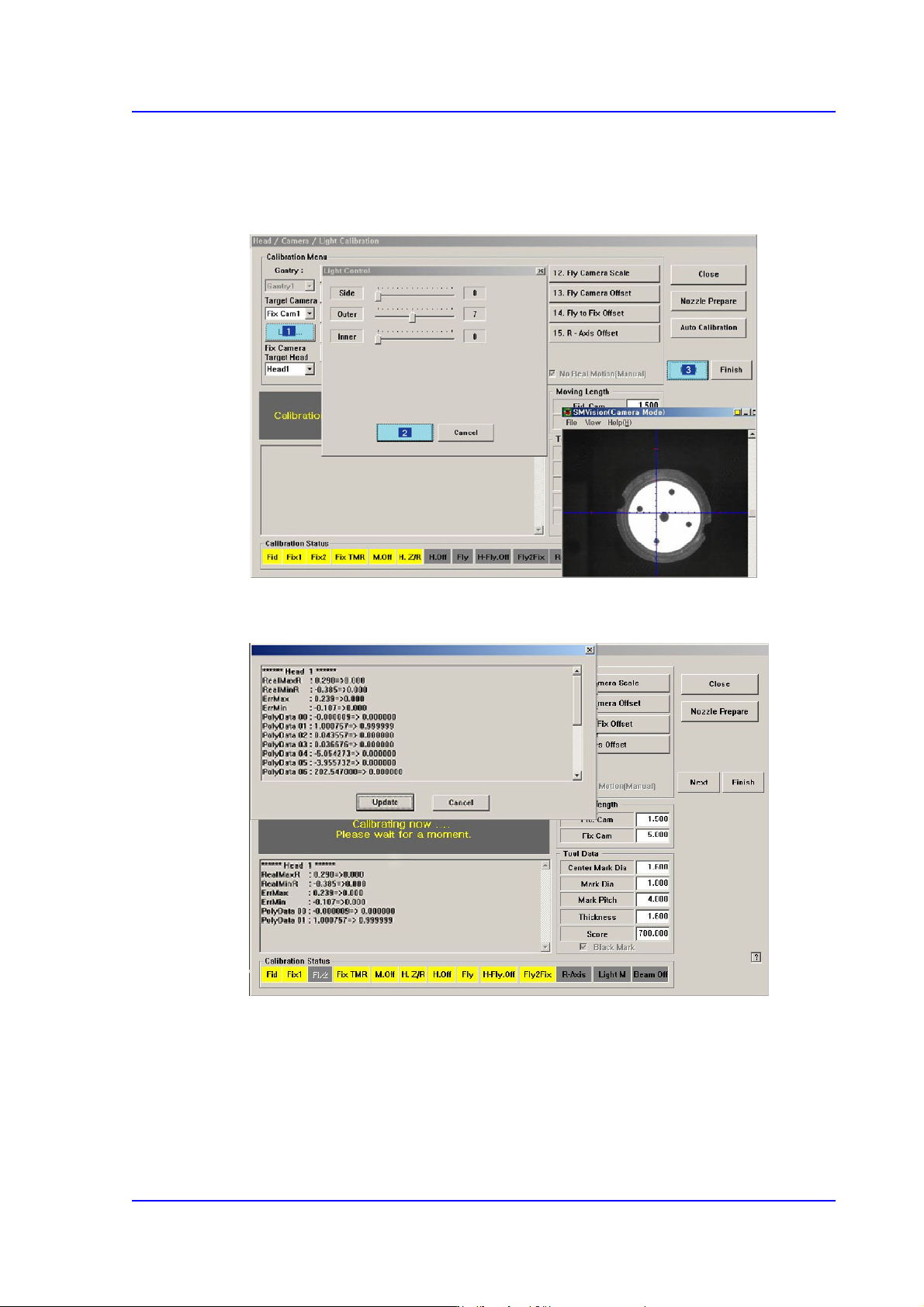
6. The message “Move To Center Position of Calibration Tool. To Move, Click [Next].”
appears. appears in the message window. Click the <Next> button to move the head
assembly to the calibration tool position on the ANC.
7. The message “Calibration is Prepared. To Calibrate, Click [Next]” appears. At this
14-77
Machine Calibration
time, At this time select the ‘Fly Cam1‘ in the <Target Camera> combo box and click
the <Light…> button and adjust the brightness of the light in the ‘Light Control’
dialog box so that the fiducial mark on the CNT20 nozzle that is seen in the
‘SMVision’ window can be seen clearly. Then click the <Next> button.
8. The calibration is performed automatically. If it is completed, the calibration result is
displayed as shown in the following figure.
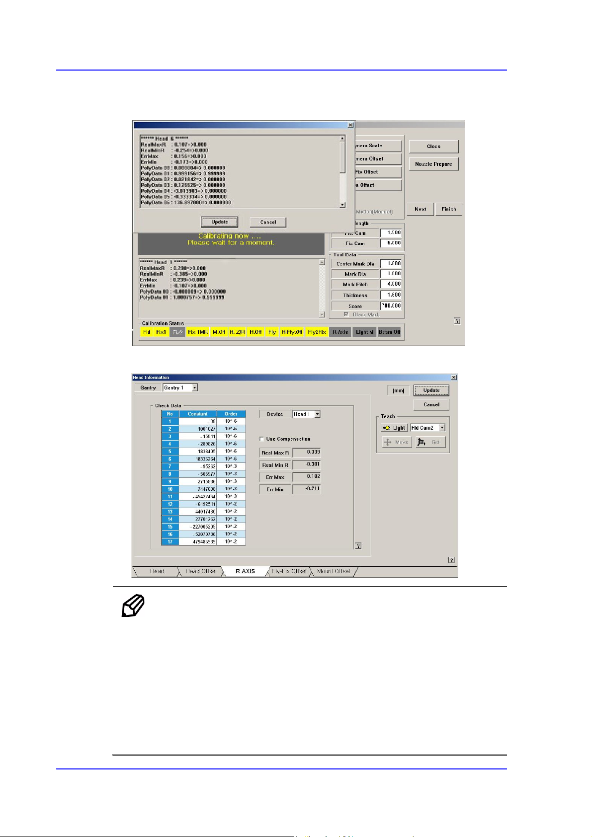
9. .For Head #2 ~ Head #6, perform calibration in the same manner as it was performed
for Head #1.
14-78
Multi-Functional Placer SM482(L) PLUS Administrator’s Guide
10. .If the calibration procedure is completed for all heads normally, the result is displayed
as shown in the following figure.
11. The measurement result can be confirmed in the R Axis dialog box.
Memo The reference values for the calibration of the R-Axis Offset is as
follows.
Real Max(Min): The Max.(Min.) offset between command value
and calibration value
Head1~Head6 : -0.500 ~ 0.500(deg)
Err Max(Min) The Max.(Min.) offset between compensation
value and calibration value
Head1~Head6 : -0.200 ~ 0.200(deg)