SM482PLUS_Admin(Eng_Ver2.8).pdf - 第510页
15-56 Multi-Functional Placer SM482( L) PLUS Administrator’s Guide 15.5.5. <Nozzle> tab dialog Sets the parameter of the fly camera when checking for the contamination of a nozzle tip. Figure15.21 “Nozzle” Tap dial…
15-55
System Setup
<Machine/ BCR> group
<Machine No.> combo box
Sets the ID so that the MES host may recognize the machine.
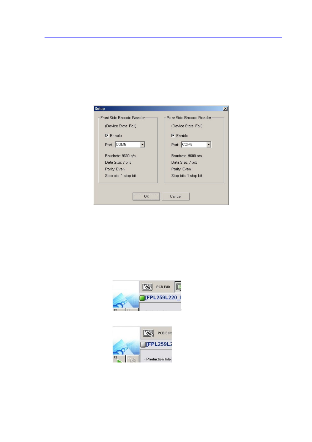
<Configure BCR...> button
Clicking this button will display the dialog box for the barcode scanner setup as
follows.
<Enable> check box
Select this check box to use the barcode reader.
<Port> combo box
Sets the port for communication between the machine and the barcode
scanner.
Check the connection status between the MES host and the machine.
When they are connected
When they are not connected
15-56
Multi-Functional Placer SM482(L) PLUS Administrator’s Guide
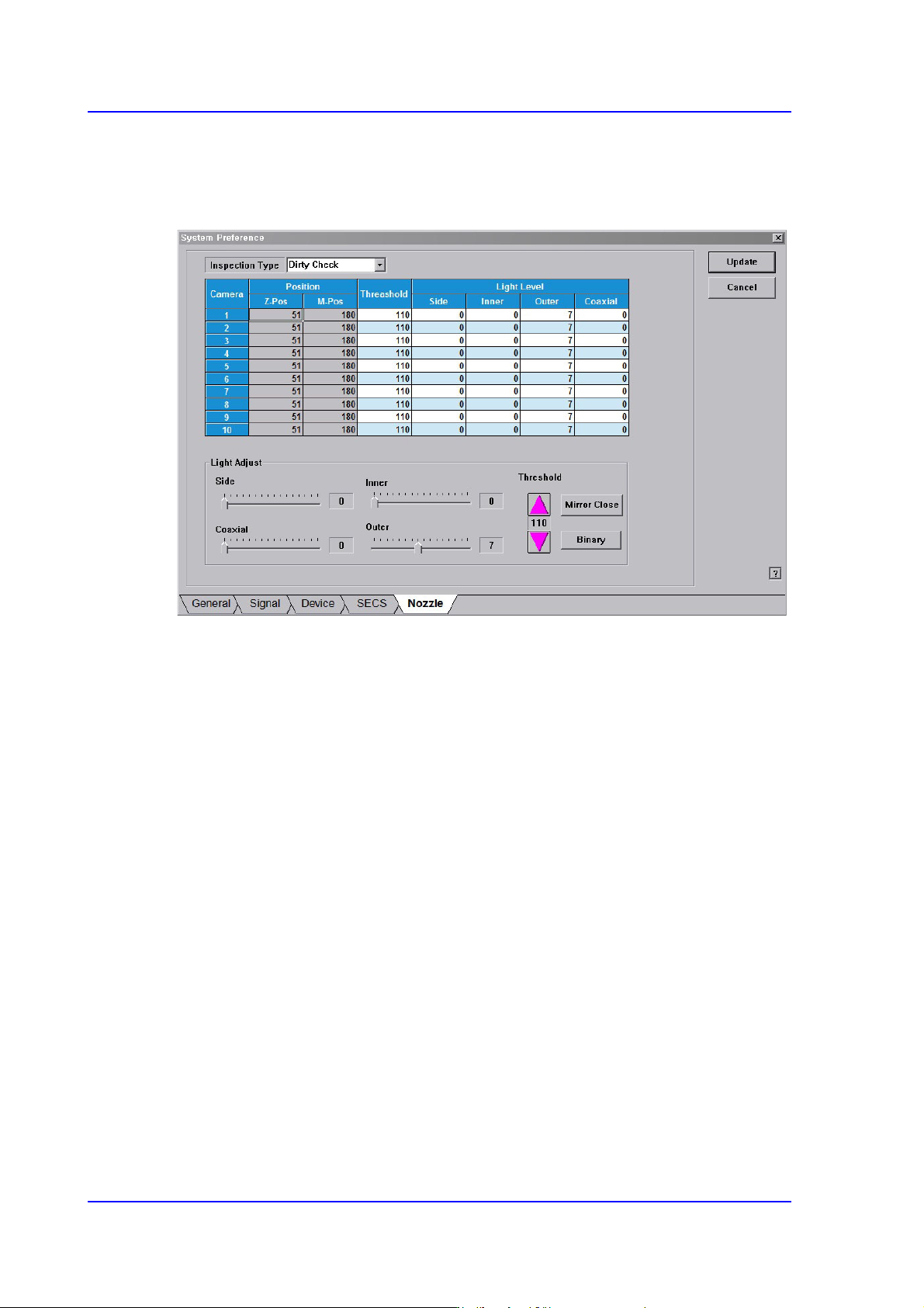
15.5.5. <Nozzle> tab dialog
Sets the parameter of the fly camera when checking for the contamination of a nozzle tip.
Figure15.21 “Nozzle” Tap dialog
<Inspection Type> combo box
Dirty Check
Selected when checking for the contamination of a nozzle tip.
Tip Check
This function is not applied to this machine.
Holder Check
This function is not applied to this machine.
<Position> group
Z-Pos
Indicates the Z-axis height from the upper surface of the PCB to the nozzle tip
end.
M-Pos
Indicates the rotation angle of the mirror for the fly camera.
<Threshold> column
Sets the threshold of the vision system used to recognized the degree of nozzle tip
contamination.
<Light Level / Light Adjust> slide bar
Sets the lighting of the fly camera.

15-57
System Setup
<Mirror Open / Mirror Close> button
Opens or closes the mirror installed on the head module. Closing the mirror will allow
a user to check the nozzle tip with a vision system.
<Binary / Real> button
Shows the image seen through the Vision in real display to which threshold is not
applied, or in the image (Binary) to which threshold is applied as recognized by MMI.