SM482PLUS_Admin(Eng_Ver2.8).pdf - 第433页
14-61 Machine Calibration 8. Then the message “ Next, Remove the Calib ration Nozzle From Head 1. Click [Next] for Moving Down Head. After Moving, Remo ve the Nozzle Manually” appears. Click the <Next> button to re…
14-60
Multi-Functional Placer SM482(L) PLUS Administrator’s Guide
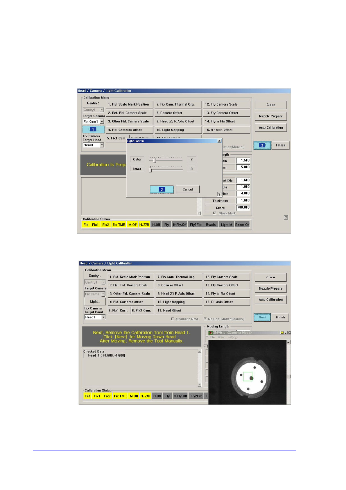
6. The message “Calibration is Prepared. To Calibrate, Click [Next]” appears. At this
time, click the <Light…> button and adjust the brightness of the light in the ‘Light
Control’ dialog box so that the fiducial mark on the calibration tool that is seen in the
‘SMVision’ window can be seen clearly. Then click the <Next> button.
7. The calibration is performed automatically. If it is completed, the calibration result is
displayed as shown in the following figure. Click the <Next> button.
14-61
Machine Calibration
8. Then the message “Next, Remove the Calibration Nozzle From Head 1. Click [Next]
for Moving Down Head. After Moving, Remove the Nozzle Manually” appears. Click
the <Next> button to remove the calibration tool from the nozzle-holder of Head #1
manually.
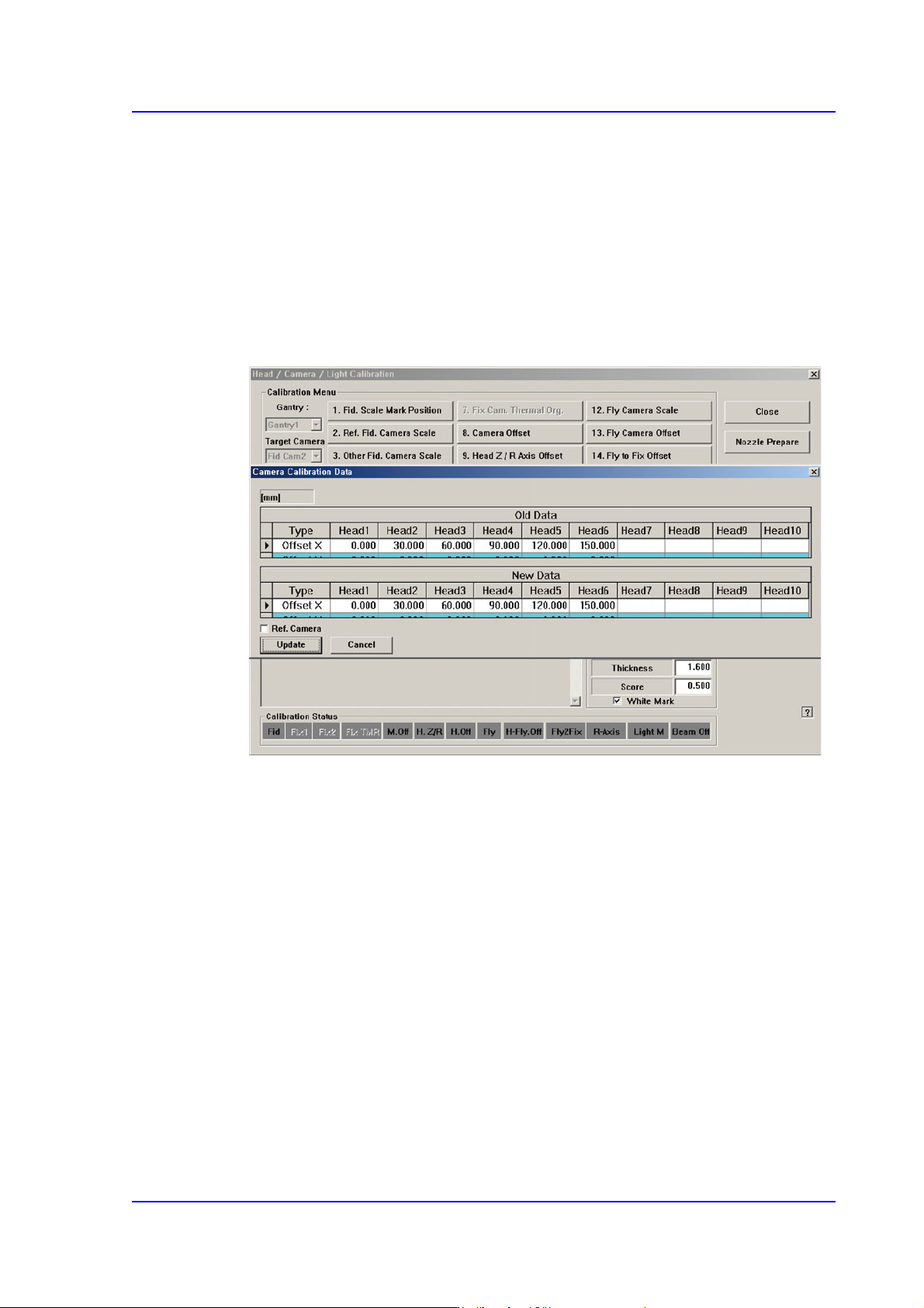
9. Form Head #2 to Head #6, perform calibration in the same manner as it was performed
for Head #1.
10. If the calibration procedure is completed for all heads normally, the result is displayed
as shown in the following figure. Click the <Update> button to apply the calibration
value.
14-62
Multi-Functional Placer SM482(L) PLUS Administrator’s Guide
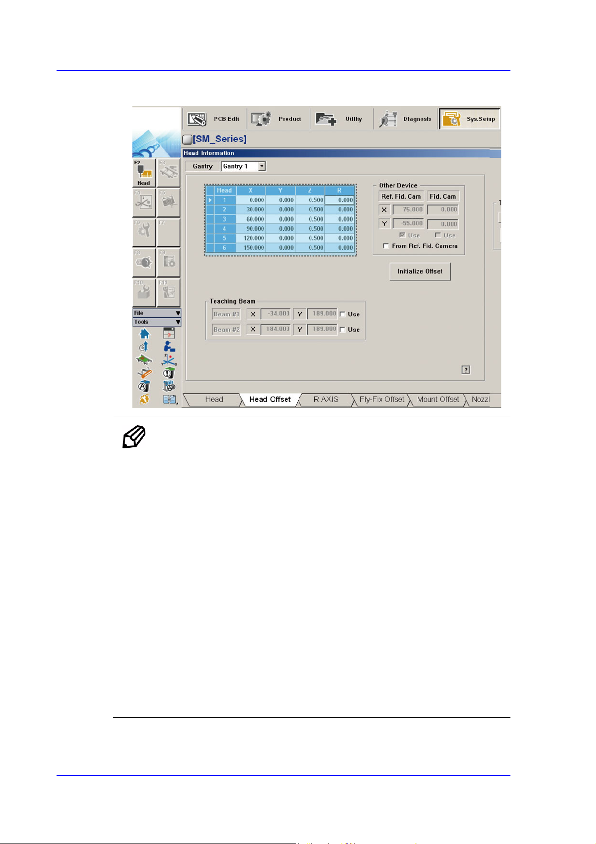
11. The measurement result can be confirmed in the Head Offset dialog box.
Memo The range of the reference value for the ‘Head Offset Calibration’ are
as follows:
Head 1
X:-0.05mm~0.05mm, Y: -0.04mm~0.04mm
Head 2
X:29.95mm~30.05mm, Y: -0.04mm~0.04mm
Head 3
X:59.95mm~60.05mm, Y: -0.04mm~0.04mm
Head 4
X:89.95mm~90.05mm, Y: -0.04mm~0.04mm
Head 5
X:119.95mm~120.05mm, Y: -0.04mm~0.04mm
Head 6
X:149.95mm~150.05mm, Y: -0.04mm~0.04mm