SM482PLUS_Admin(Eng_Ver2.8).pdf - 第528页
16-8 Multi-Functional Placer SM482( L)P PLUS Administrator’s Guide 16.4. Vacuum [F5] Checks the air pressure status of the head. Figure16.7 “Vacuum Diagnosis” di alog box <Head V acuum level> group Displays the v…

16-7
Diagnosis
<Light Value> group
Set the light value.
When the fiducial camera is selected, the range of light level that can be set is as
follows.
<Outer>: The range of the Outer light level is 0~15.
<Inner>: The range of the Inner light level is 0~15.
When the fly camera is selected, the range of light level that can be set is as follows.
<Side>: The range of the side light level is 0~15.
<Outer>: The range of the Outer light level is 0~15.
When the fix camera is selected, the range of light level that can be set is as follows.
<Side>: The range of the side light level is 0~15.
<Outer>: The range of the Outer light level is 0~15.
<Inner>: The range of the Inner light level is 0~15.
<Close> button
Closes the dialog box.
16-8
Multi-Functional Placer SM482(L)P PLUS Administrator’s Guide
16.4. Vacuum [F5]
Checks the air pressure status of the head.
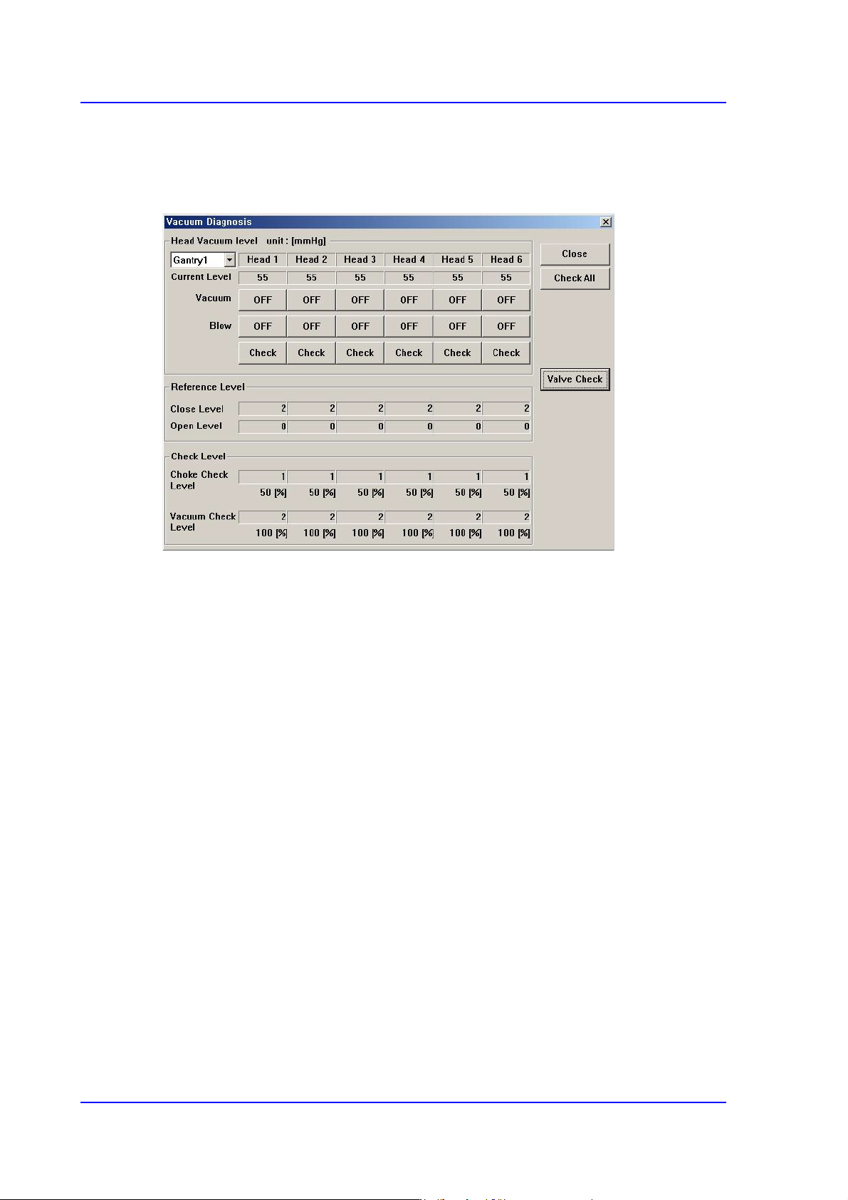
Figure16.7 “Vacuum Diagnosis” dialog box
<Head Vacuum level> group
Displays the vacuum level of each head and controls the vacuum generator.
<Gantry> combo box
Select the gantry for which the pneumatic pressure can be checked.
<Current Level>
Indicate the current pneumatic pressure of each head.
<Vacuum OFF> button
Pressing this button when “OFF” is indicated will supply constant pneumatic
pressure of 0.1Mpa inside the spindle and indicate “ON” on the button.
<Blow OFF> button
Pressing this button when “On” is indicated will shut off the pneumatic pressure
supplied to the spindle and indicate “OFF” on the button.
<Reference Level> group
When the vacuum level is used as a criteria for determining the component pick-up by
each head, displays the standard value.
<Close Level>
Indicate the pneumatic pressure of each head when the nozzle hole is plugged,
with the nozzle being inserted into the nozzle holder.
16-9
Diagnosis
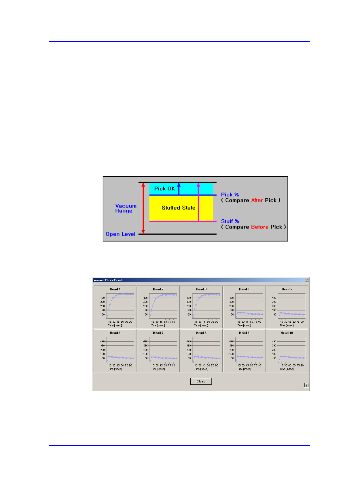
<Open Level>
Indicate the vacuum value of each head when the nozzle hole is opened, with the
nozzle being inserted into the nozzle holder.
<Check Level > group
Displays the vacuum level that is used as a criteria for determining the component
pick-up.
<Choke Check Level>
Displays the vacuum level that considers the nozzle to be choked up before the
component pick-up.
<Vacuum Check Level>
Displays the vacuum level that considers a pickups to be successful after the
component pick-up.
<Check All> button
Measure the time that it takes until the vacuum value becomes stabilized for all heads
of the selected gantry.