SM482PLUS_Admin(Eng_Ver2.8).pdf - 第248页
7-76 SM PLUS Administrator’s Guide <Placement> tab Sets the parameters rela ted to part placement. <Soft T ouch> combo box This can be applied for the part pickup an d placement. It allows the speed of th…

7-75
Part Registration
the part or affect the part, causing a problem.
The 'Soft Touch' function may be used together if necessary. For this
function, refer to the description of the <Placement> tab.
<Z Place Up> Selection button
When moving up the head spindle after part placement, selects the driving
speed of the Z-axis motor.
If the speed is inappropriate depending on the parts, it may have an
undesirable effect on placement accuracy.
The 'Soft Touch' function may be used together if necessary. For this
function, refer to the description of the <Placement> tab.
<Z Align Speed>
Sets the speed at which the head spindle moves up/ down for the fix
camera to recognize a part.
Setting the placement speed (up/down) to slow considering placement
accuracy will require more time to move to the Z-axis recognition height.
In order to overcome this problem, the function to designate the speed of
the above two movements is added.
In the case of micro parts to which a pickup error according to the speed at
which the Z-axis moves down, perform a part recognition test changing
the speed and register the Z-axis speed when part recognition is
successfully performed.
<Tray Pallet Speed> group
<Pallet In /Out Speed> option box
Corresponds to the case that the tray feeder is selected in the <Feeder>
selection control. Select the pallet movement speed of the tray feeder when
supplying parts. The types of pitches that can be selected are as follows: (1:
Fastest, 5: Slowest)
<Pallet Up /Down Speed> option box
Corresponds to the case that the tray feeder is selected in the <Feeder>
selection control. Sets the up/down movement of the pallet of a tray feeder
when supplying parts. The types of pitches that can be selected are as follows:
(1: Fastest, 5: Slowest)
7-76
SM PLUS Administrator’s Guide
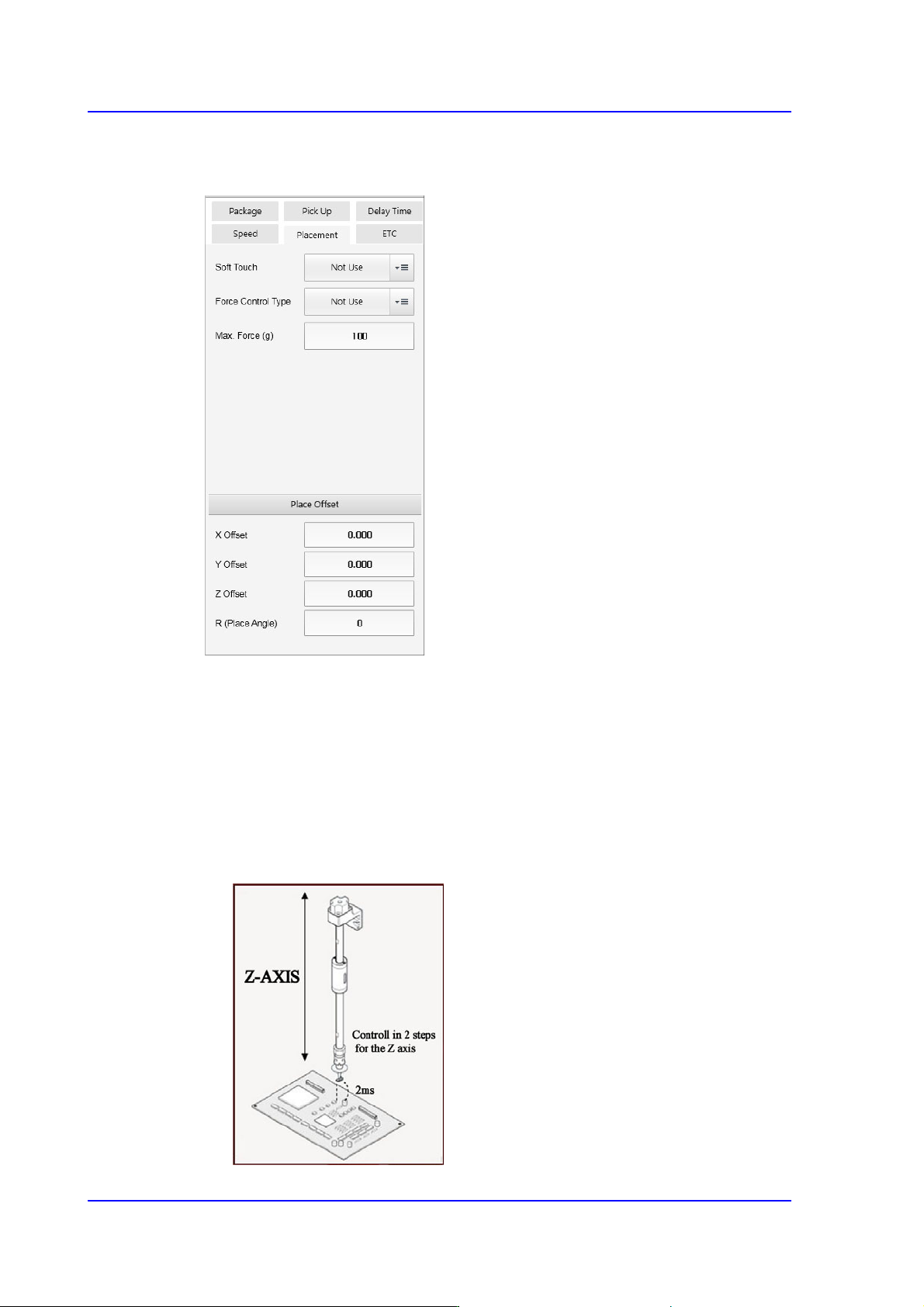
<Placement> tab
Sets the parameters related to part placement.
<Soft Touch> combo box
This can be applied for the part pickup and placement. It allows the speed of the Z
axis to become 4 (slow) at 2mm height from the PCB upper surface when the head
moves down regardless of the speed set in the <Speed> group.
That is, the speed is controlled in 2 steps for the Z axis. For example, if cracks
occur frequently in the part. The overall speed of the Z axis may be reduced.
However, in this case, overall efficiency decreases.
At this time, the work can be done efficiently using this function.

7-77
Part Registration
Not Use: Set this function so that it is not used.
Pick: Set this function so that it is used only for pickup.
Mount: Set this function so that it is used only for placement.
Pick&Mount: Set this function so that it is used only for pickup and
placement.
Caution In case of shock sensitive components like CSP or μBGA,
the z-axis related speed parameters must be set according
to the component manufacturer’s specification or standards.
And use the nozzle suitable to component manufacturer’s
specification or standards.
If necessary, please contact our Business Department or
the local agent for the nozzle suitable to component
manufacturer’s specification or standards.
<Force Control Type> selection box
Select the method to control the force imposed on the part when the head spindle
moves down for part pickup or placement.
This function is supported for machines equipped with a head module that
provides a force control function.
Not Use
Selected in cases to setup so the force control function will not be used.
Pickup
Selected in cases to setup so that the force control function will be applied
only for part pickup.
Place
Selected in cases to setup so that the force control function will be applied
only for part placement.
Both
Selected in cases to setup so that the force control function will be applied
only for part pickup and placement.
<Max. Force (g)> edit box
Input the maximum force controlled by the head module.
If a PIP part is not inserted into a PCB hole by 1 kg of force, perform a PIP part
insert test by increasing the force by 500g each time.
<Place Offset> group
It is possible to set the part placement offset.