SM482PLUS_Admin(Eng_Ver2.8).pdf - 第370页
13-22 Multi-Functional Placer SM482( L) PLUS Administrator’s Guide 13.7. PCB D/L [F7] T ransmits the PCB data set in the <PCB Edit> menu to the equipment. T ransmission is possible only when the equi pment status i…

13-21
Production Setup
<Grid> group
Set the position of the pocket to start.
<Step> column
Displays the number of tray step.
<X> column
Set the X position of the pocket.
<Y> column
Set the Y position of the pocket.
<Remain> column
Indicates the number of parts remaining in the corresponding pallet.
<Reset> column
After refilling components for empty pallets, Clicking this button initializes the
pocket position to start (X=1, Y=1) on each pallet.
<Part> column
Displays the name of the component supplied the Tray
<All Reset> button
Initializes the pickup point for upper pallets to the first pocket (X = 1, Y = 1).
<Refill All> button
Clicking this button after resupplying those lower pallets which have run out of parts
will initialize the pickup position to the first pocket (X = 1, Y = 1) for each pallet.
<OK> button
Transmits the set data to the equipment and closes the dialog box.
<Cancel> button
Ignores the set data and closes the dialog box.
13-22
Multi-Functional Placer SM482(L) PLUS Administrator’s Guide
13.7. PCB D/L [F7]
Transmits the PCB data set in the <PCB Edit> menu to the equipment. Transmission is
possible only when the equipment status is “Finish”.
13.8. Pd. Info [F8]
Displays placement operation data for head, nozzle and feeder. Please refer to “18.1
Production Information Management [Pd. Info]” for more information.
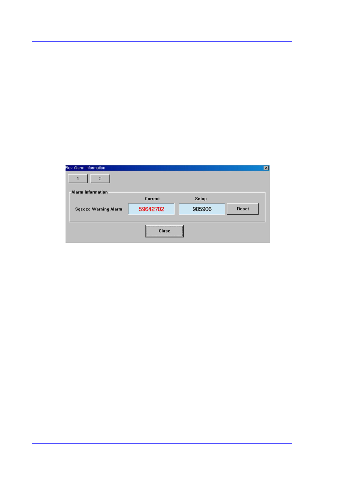
13.9. Flux. [F9]
Perform setup for the warning message related to the operation of the flux module.
<Squeeze Warning Alarm>
Clicking the <Reset> button will initialize the set flux module cleaning cycle. The
setup of the corresponding item can be performed in the ‘Flux’ tab dialog box in the
‘Periph.’ submenu of the ‘Sys.Setup’ menu.

Calibration & Setup