SM482PLUS_Admin(Eng_Ver2.8).pdf - 第423页
14-51 Machine Calibration 14.3.7.3. Camera Offset Calibration Measure the offset between the center of the fiducia l camera and the first head (He ad 1) of each gantry . This offset measurement must be completed to be ab…
14-50
Multi-Functional Placer SM482(L) PLUS Administrator’s Guide
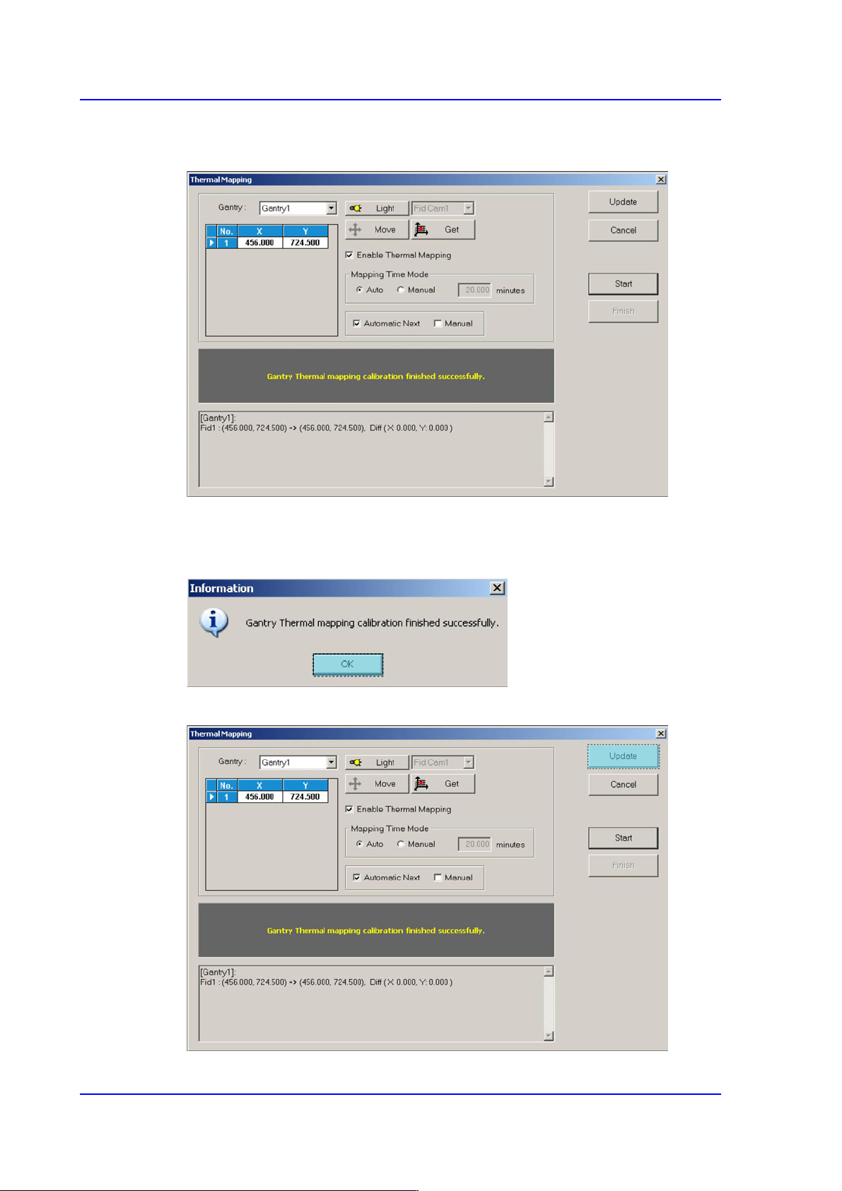
4. Once the <Start> button is clicked after selecting <Automatic Next>, the equipment
automatically performs calibration.
5. Once automatic calibration is completed, a message "Gantry Thermal mapping
calibration finished successfully" is displayed, showing result value as indicated in the
following figure.
6. Click <Update> button to apply the new calibration value.
14-51
Machine Calibration
14.3.7.3. Camera Offset Calibration
Measure the offset between the center of the fiducial camera and the first head (Head 1) of
each gantry.
This offset measurement must be completed to be able to use the Auto Nozzle Change
function for calibrations that follow. This process is performed only in the Manual Mode.
A calibration glass must be used to perform this calibration and calibration is required only
for a single fix camera even if there are two fix cameras.
Calibration using a calibration glass (fix camera option)
The following is the procedure to calibrate the Fid Cam Offset of the head;
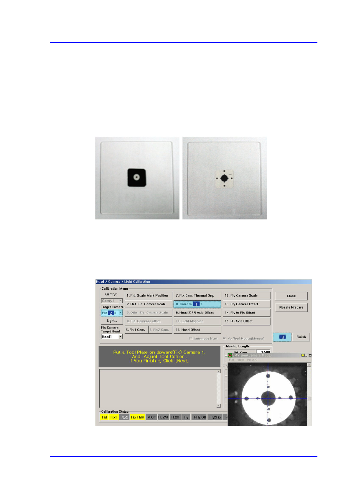
1. If the <8. Camera Offset> button is clicked, the message “Put a Tool Plate on
Upward(Fix) Camera 1. And Adjust Tool Center. If you Finish it, Click [Next].”
appears in the message box. Click the <Next> button to move down the Z axis of the
head in order to remove all nozzles inserted in the nozzle-holder manually.
14-52
Multi-Functional Placer SM482(L) PLUS Administrator’s Guide
Memo Only when the Calibration Glass is properly aligned with the center of
the Fix Camera can calibration be performed. Place the Calibration
Glass correctly referring to the following figure.
2. The message, “Move To Center Position of [Fix 1] Camera. To Move, Click [Next]” is
displayed in the message window. Click the <Next> button to move the head assembly
to the center of the Fix 1 Camera.
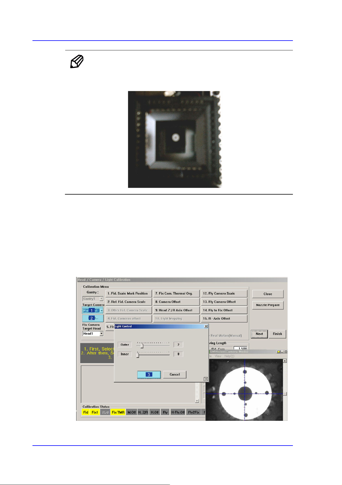
3. The message “1. First, Select Move Camera and Adjust Light Level. 2. After that,
Select Fix-camera and Adjust Light Level. 3. To Calibrate, Click [Next]” appears.
Then click the <Light…> button first and adjust the brightness of the light in the Light
Control’dialog box so that the white circle at the center of the Calibration Glass that is
seen in the ‘SMVision’ window can be seen clearly.