SM482PLUS_Admin(Eng_Ver2.8).pdf - 第482页
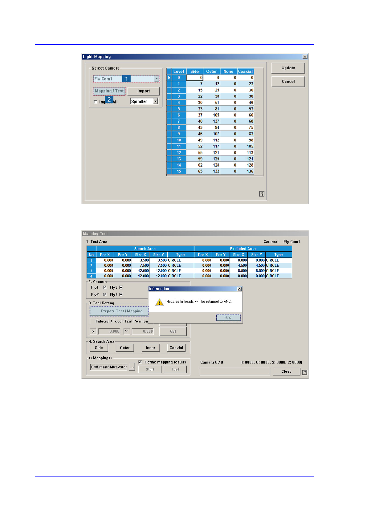
15-28 Multi-Functional Placer SM482( L) PLUS Administrator’s Guide 2. After unchecking the <Manual> check box in the <3. T ool Setting> group, click the <Prepare T est / Mapping> button.
15-27
System Setup
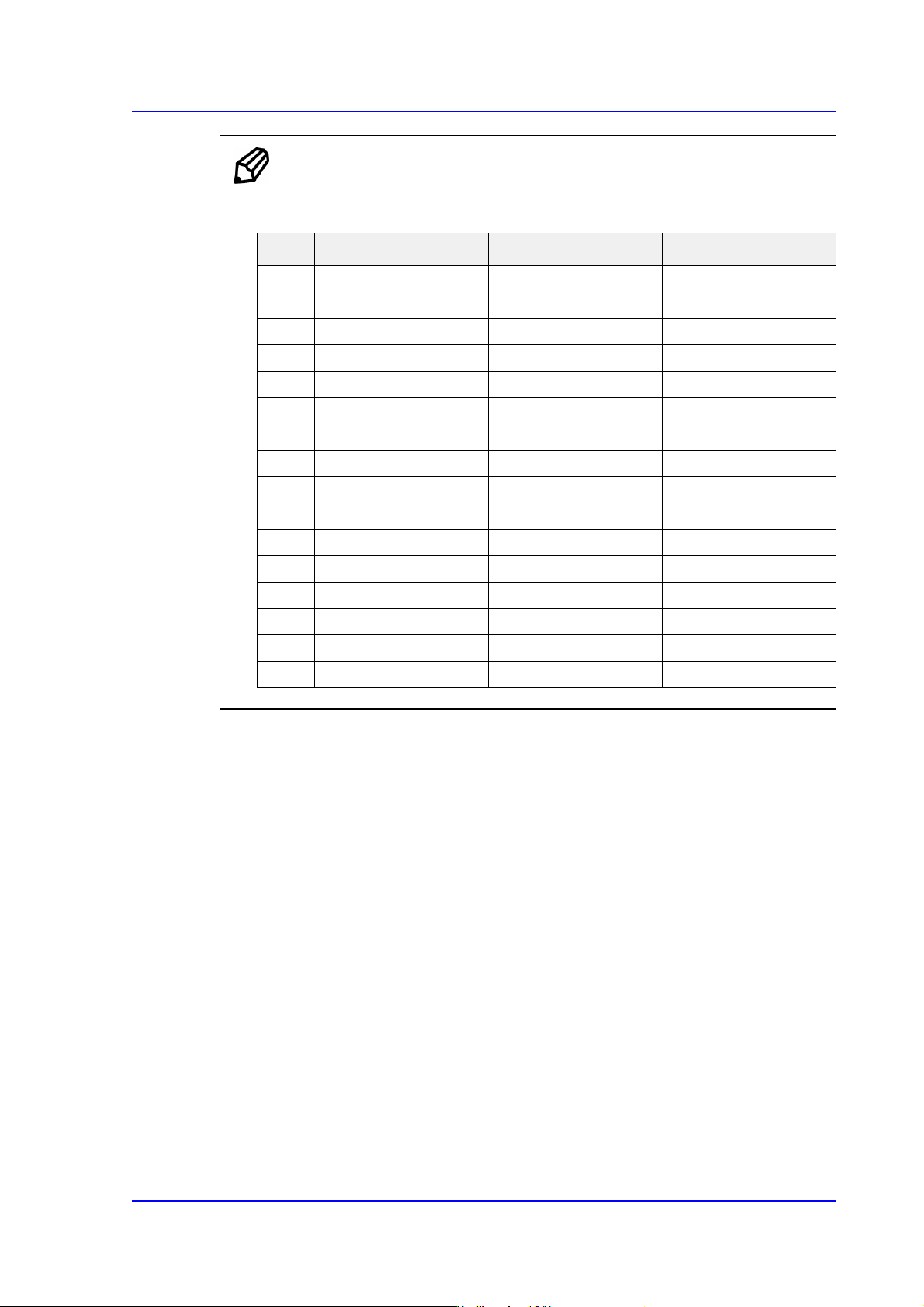
Ref. The test result value must be within ±10 from the following reference
value.
Perform light mapping of the Fly Camera in the following manner:
1. After selecting the camera for which light mapping is to be performed in the <Select
Camera> group, click the <Mapping/Test> button.
Side Outer Inner
0121212
1252323
2393335
3514245
4625154
5736064
6867075
7967985
8 105 87 94
9 115 95 102
10 125 103 112
11 135 111 121
12 143 118 128
13 151 125 136
14 160 133 145
15 168 140 152
15-28
Multi-Functional Placer SM482(L) PLUS Administrator’s Guide
2. After unchecking the <Manual> check box in the <3. Tool Setting> group, click the
<Prepare Test / Mapping> button.
15-29
System Setup
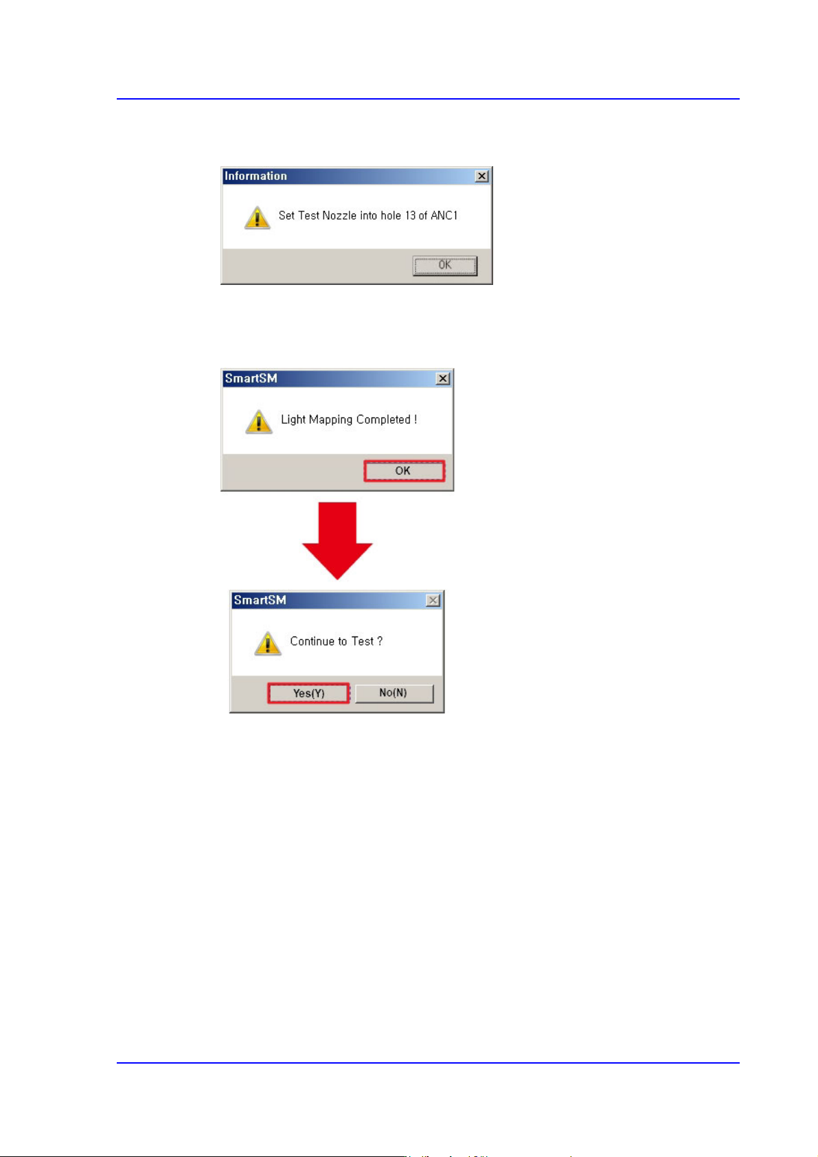
3. After inserting the Fly Camera Test nozzle into the ANC 13 hole, press the <OK>
button.
4. After clicking the <Start> button in the <<Mapping>> area, when the Light Mapping
is finished, the following dialog box appears. Pressing the <OK> button will display
the dialog box for the test.
5. Click the <(Y)> button to perform the test automatically.