SM482PLUS_Admin(Eng_Ver2.8).pdf - 第98页
4-10 Multi-Functional Placer SM482( L) PLUS Administrator’s Guide Head 1 ~ Head 6: Select #1 ~ #6 heads. <Move> button Move the object selected in the Combo Box to the positio n of the assigned coordinates. At …
4-9
Tools Shortcut Menu
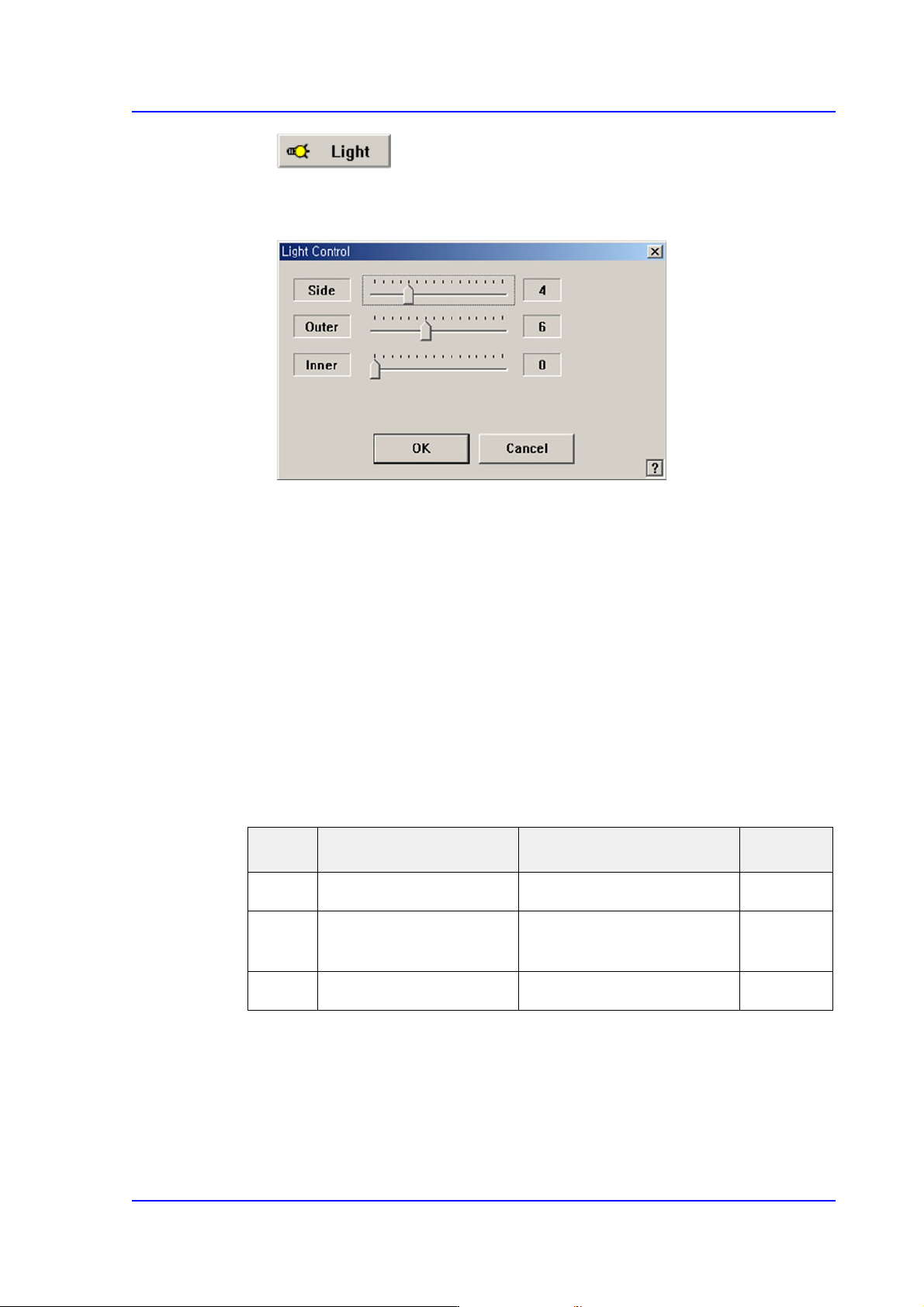
Button
Setup illumination of fiducial camera to be used for teaching. When this Button is
clicked on, the following dialog box is displayed.
<Side> slide bar
Set a value for the side light. (0 –15)
<Outer> slide bar
Set a value for the outer light. (0 - 15)
<Inner> slide bar
Set a value for the outer light. (0 - 15)
<OK> button
Saves the set light value and closes the dialog box.
<Cancel> button
Closes the dialog box without saving the set light value.
Table4.1 Use of the Fix Camera Lighting
Combo Box
Used for selecting the object to move to the designated coordinates by rotating the
XY axis driving motor or to select the object for which the present coordinates is
searching. Selectable objects are as follows;
Fid Cam1: Select the fiducial camera on the front gantry.
Light Use Applicable Part Remarks
Side Lights the edge of a part Chip, QFP, BGA, SOP etc
Outer Lights round edge of a
part or part surface
Chip, QFP, BGA, SOP etc
Inner Lights a part surface Chip, QFP, BGA, SOP etc

4-10
Multi-Functional Placer SM482(L) PLUS Administrator’s Guide
Head 1 ~ Head 6: Select #1 ~ #6 heads.
<Move> button
Move the object selected in the Combo Box to the position of the assigned
coordinates. At this time, before executing <Move> button, the hole
corresponding to the desired position must be clicked on with a mouse.
<Get> button
Obtain coordinates for XY axis with reference to the object selected in the Combo
Box. At this time, before executing <Get> button, the hole corresponding to the
desired position must be clicked on with a mouse.
<Fiducial Mark Detail…> button
Set the ANC fiducial mark data. For more details. refer to Section “6.3. Fiducial Mark
Setup”.
<Move Next Hole> button
Moves the device selected from the Combo Box in <Teach> group to the hole next to
the currently selected hole in the ANC.
<Shutter Open/Close> button
When this Button is clicked on, the ANC shutter is Opened or Closed.
<Head-Inspect Nozzle Type> button
Clicking this Button will perform the inspection of the type of the nozzle inserted in
the nozzle holder of the currently selected head. Since separate setup is needed to
enable this function, our C/S department must first be contacted.
The nozzles whose types can be checked are as follows:
CN030, CN040, CN065, CN140, CN220
<All-Inspect Nozzle Type> button
Clicking this Button will inspect the types of nozzles inserted in the nozzle holders of
all heads. Since separate setup is needed to enable this function, our C/S department
must first be contacted.
The nozzles whose types can be checked are as follows:
CN030, CN040, CN065, CN140, CN220
<Pick & Put> group
<No real motion> check box
When this Button is checked, manipulates the data for pick and put functions
without actual operation.
<Pick> button
When this Button is clicked on, picks up the nozzle in the currently selected hole
of the ANC. Select the head to pick in the Combo Box in the <Teach> group.
<Put> button
4-11
Tools Shortcut Menu
When this Button is clicked on, puts the nozzle in the head selected in the
“Device” to ANC.
<Put all nozzle> button
When this Button is clicked on, puts the nozzles in all the heads to the ANC.
<View All Nozzles / Move Heads Safe> button
Used to move down the Z axis of all heads of the selected gantry of certain height so as
to check visually if any nozzle exists on the nozzle head.
After the visual check, if clicked again, Z axes of all heads are moved up to the
original position.
<Different ANC Info.In Current PCB file> list box
Shows the difference between the ANC setting of the currently loaded PCB file and
the ANC setting of the currently working equipment system. To change the system
setting to the PCB file setting, click on the <PCB->System> button on the right and
change the nozzles in other holes with different settings to fit the setting.
<PCB->System> button
Change the system setup to the PCB file setup
Warning When Manual ANC movement is executed, the nozzle of
the head and other areas of the machine might collide
unless the programmed nozzle and the actual nozzle
coincide. Be sure to match the programmed nozzle and the
actual nozzle in the machine.
<Close> button
Pressing this Button will save the changed setup and close the current dialog box.