SM482PLUS_Admin(Eng_Ver2.8).pdf - 第425页
14-53 Machine Calibration 4. Then select the ‘Fix1 Cam’ in the <T arget Camera> combo box and click the <Light…> button. Adjust the br ightness of the ligh t in the ‘Light Control’ dialog box so that the fidu…
14-52
Multi-Functional Placer SM482(L) PLUS Administrator’s Guide
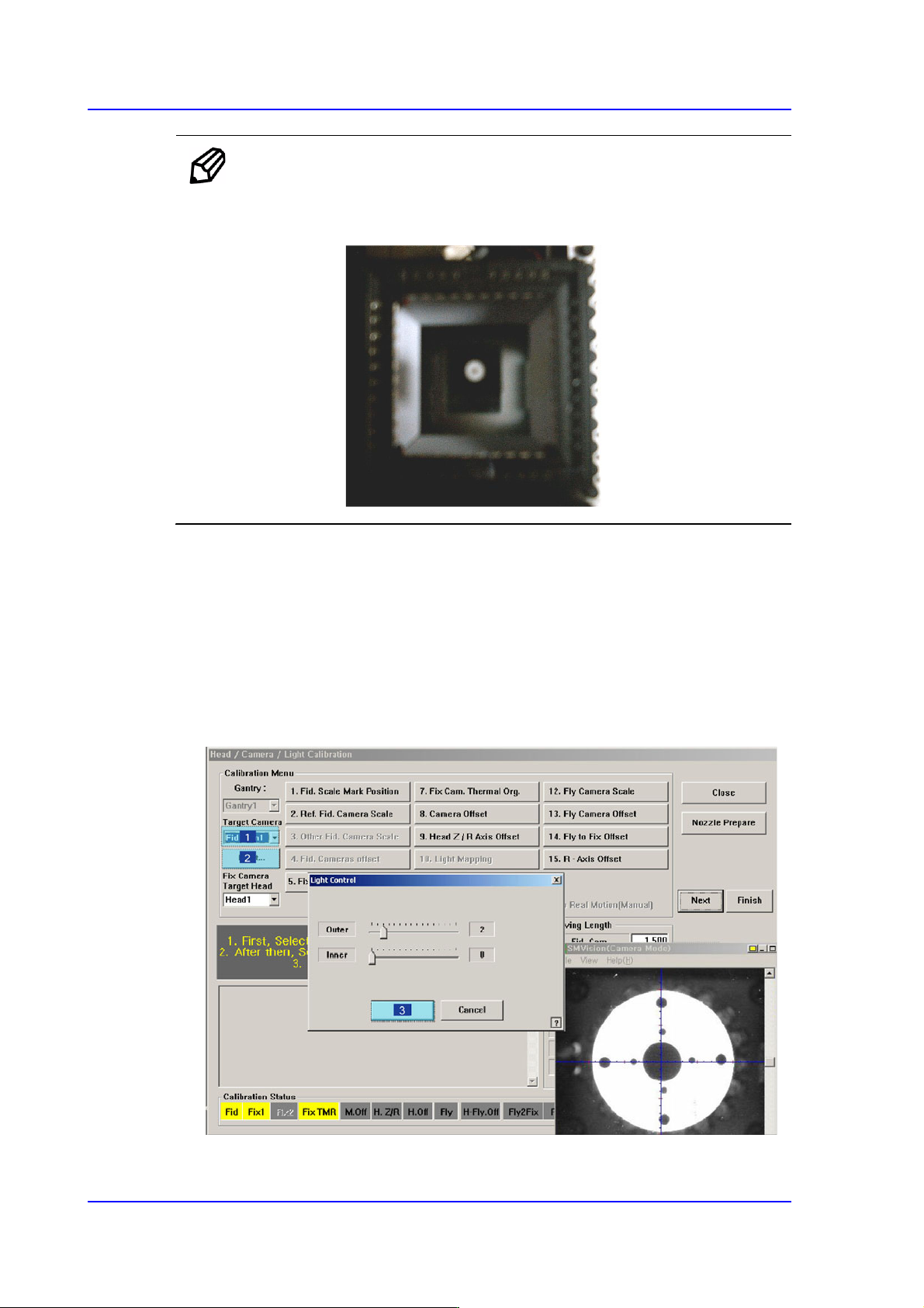
Memo Only when the Calibration Glass is properly aligned with the center of
the Fix Camera can calibration be performed. Place the Calibration
Glass correctly referring to the following figure.
2. The message, “Move To Center Position of [Fix 1] Camera. To Move, Click [Next]” is
displayed in the message window. Click the <Next> button to move the head assembly
to the center of the Fix 1 Camera.
3. The message “1. First, Select Move Camera and Adjust Light Level. 2. After that,
Select Fix-camera and Adjust Light Level. 3. To Calibrate, Click [Next]” appears.
Then click the <Light…> button first and adjust the brightness of the light in the Light
Control’dialog box so that the white circle at the center of the Calibration Glass that is
seen in the ‘SMVision’ window can be seen clearly.
14-53
Machine Calibration
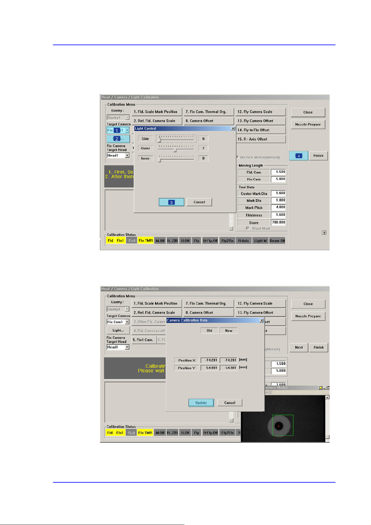
4. Then select the ‘Fix1 Cam’ in the <Target Camera> combo box and click the
<Light…> button. Adjust the brightness of the light in the ‘Light Control’ dialog box
so that the fiducial mark on the Calibration Glass that is seen in the ‘SMVision’
window can be seen clearly. Click the <Next> button..
5. The calibration is performed automatically. If it is completed, the calibration result is
indicated as shown in the following figure. Click the <Update> button to apply the
calibration value.
14-54
Multi-Functional Placer SM482(L) PLUS Administrator’s Guide
6. If the calibration procedure is completed properly, the result as shown in the following
figure is displayed and then the message, “Move (Fiducial/Teach) Camera Offset is
Finished. Remove Tool Plate!” appears. At this point, remove the flat board calibration
tool placed on the Fix 1 Camera. Otherwise, damages may be caused by collision with
the head.
Memo The reference values for the calibration of the Camera Offset is as
follows.
Camera Offset (FOV 12)
Offset X : -76.0mm ~ -74.0mm
Offset Y : 54.0mm ~ -56.0mm
14.3.7.4. Head Z / R Offset Calibration
The distance from the upper surface of the PCB to the Z axis home is set mechanically. For
the Z offset calibration, measure the offset for this distance based on the upper surface of
the PCB by using pneumatic pressure.
For the R offset calibration, measure the offset of the angle to align the nozzle holder
based on zero (0) degrees.
The following is the process that the Z offset calibration is performed. The nozzle used for
calibration is the CN040 nozzle.
1. Click the <Head Z / R Axis Offset> button.
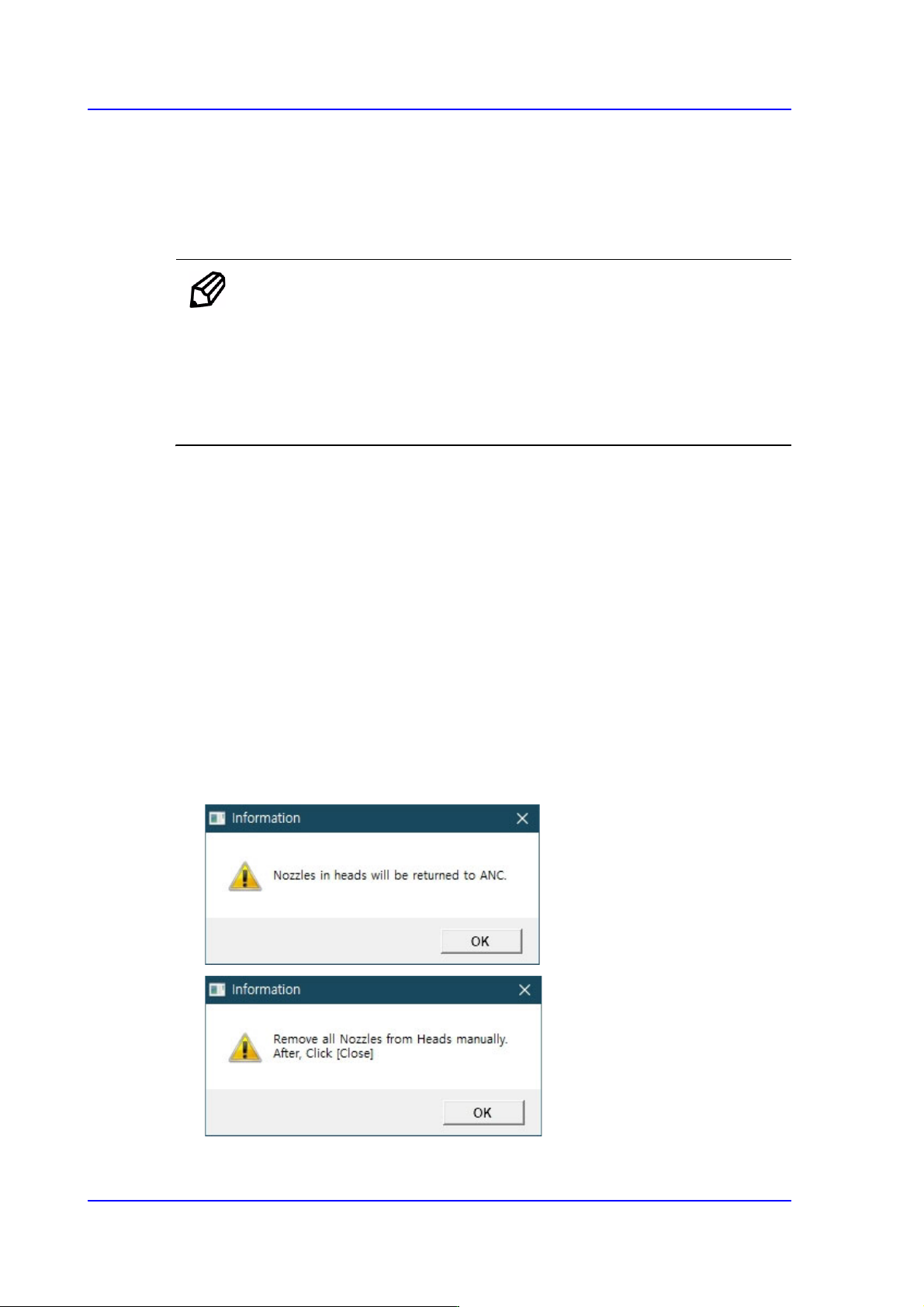
2. Click the <Nozzle Prepare> button and remove all nozzles inserted in the nozzle
holders of all heads. Insert the CN040 nozzle into the No. 14 hole of the ANC.