SM482PLUS_Admin(Eng_Ver2.8).pdf - 第127页
6-9 Board Definition 2) When part placement is not po ssible When there is a bad/accept mark or a 2D barcode in the second placement area If the bad/accept mark or the 2D barcode cannot be recognized in the first place…
6-8
Multi-Functional Placer SM482(L) PLUS Administrator’s Guide
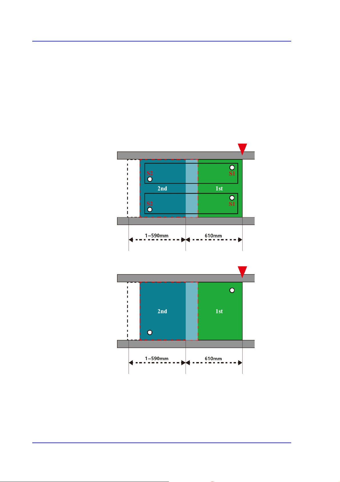
1) When part placement is possible but placement accuracy is poor
At least two fiducial marks are required within a placement area,
but if there is only a single fiducial mark within a placement area,
this equipment can use the fiducial mark to calibrate just the X
and Y coordinates, but cannot calibrate the theta coordinates.
Therefore, the two or three-level placement method is not
recommended for IC parts, which require a high level of
accuracy.
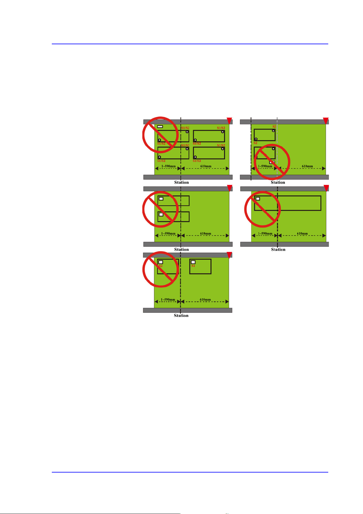
When the array or block fiducial mark is overlapping across
two placement areas
When there are only two panel fiducial marks
6-9
Board Definition
2) When part placement is not possible
When there is a bad/accept mark or a 2D barcode in the
second placement area
If the bad/accept mark or the 2D barcode cannot be
recognized in the first placement area, you cannot use the
bad/accept mark or the 2D barcode.
6-10
Multi-Functional Placer SM482(L) PLUS Administrator’s Guide
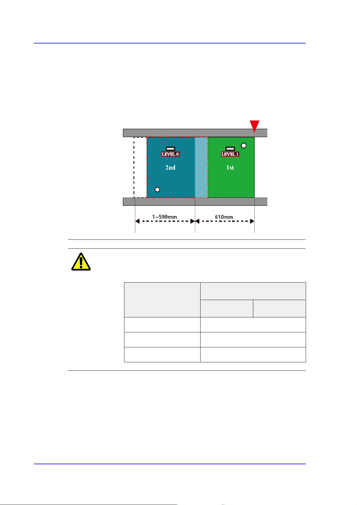
When a part with lower placement priority exists in the first
placement area
You must set the placement level of the parts if there is any
interference with the placed parts nearby depending on the
placement order. When a part with lower placement level
exists in the first placement area, a cycle NG error will occur
and the PCB program cannot be created.
Memo The specifications of the buffer that can be used in the
equipment are as follows.
<8. Handling> group
Set the data necessary for PCB operation.
<Move Z>
After the part is picked up, set the head moving height with the surface of the PCB
being “0” when moving the head.
The default value is 4mm. However, if the placed part height is higher than 4mm,
input the height part in mm unit when it is placed on the PCB.
Category
Buffer(Board) Size
Entry Zone Exit Zone
L460mm, L510mm ~ L460mm
L610mm, L660mm 610mm / 660mm
L1,200mm 540mm