SM482PLUS_Admin(Eng_Ver2.8).pdf - 第124页
6-6 Multi-Functional Placer SM482( L) PLUS Administrator’s Guide Fid Cam1: Select the fiducial camera on the fro nt gantry . Head 1 ~ Head 6: Select #1 ~ #6 heads. <Move> button Move the object selected in th…
6-5
Board Definition
<Origin X> edit box
Set the X value of the placement origin of PCB.
<Origin Y> edit box
Set the Y value of the placement origin of PCB. Click on <Origin X> or <Origin
Y>, then click on the “Move” or “'Get” Button in the <8. Teach> group, Teaching
of placement origin is possible based on the selected object from the Combo Box.
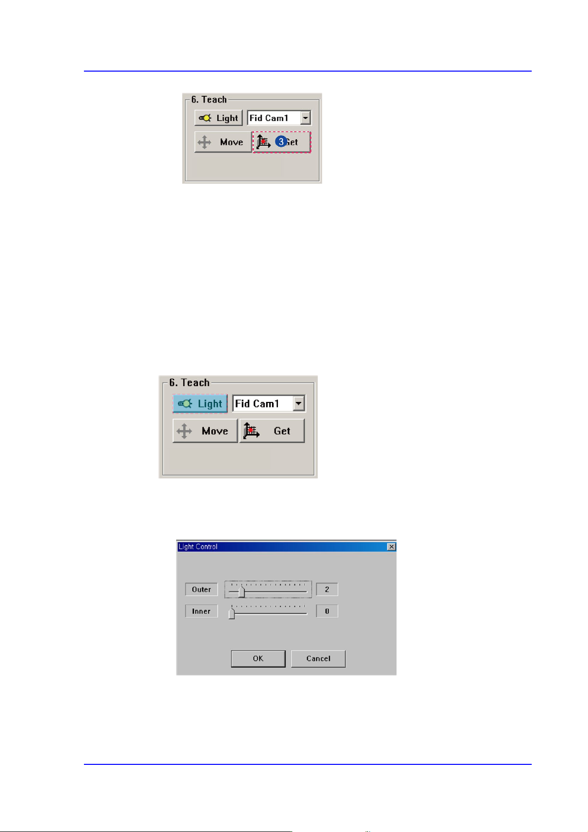
<6. Teach> group
Used for moving the selected object from the Combo Box to the position of assigned
coordinates, or for obtaining the present coordinates by rotating the XY, Z axis driving
motor.
<Light> button
Sets the lighting for the fiducial camera. When this Button is clicked on, the
following dialog box is displayed.
Combo Box
Used for selecting the object to move to the designated coordinates by rotating the
XY, Z axis driving motor or to select the object for which the present coordinates
is searching. Selectable objects are as follows;
6-6
Multi-Functional Placer SM482(L) PLUS Administrator’s Guide
Fid Cam1: Select the fiducial camera on the front gantry.
Head 1 ~ Head 6: Select #1 ~ #6 heads.
<Move> button
Move the object selected in the Combo Box to the position of the assigned
coordinates. Before clicking on the <Move> button, the objects (Place Origin,
Move Z) related with the coordinates must first be clicked with the mouse.
<Get> button
Obtain coordinates for XY, Z axis with reference to the object selected in the
Combo Box. At this time, the objects (Place Origin, Move Z) related with
coordinates must first be clicked with the mouse before clicking on the <Get>
button.
<7. Board Size> group
Set the board size.
<X> edit box
Set the length of PCB size.
<Y> edit box
Set the width of PCB size.
<Conv.Width > button
Adjust the conveyor width according to the set width of the PCB.
Memo The sizes of PCB applicable for this machine are as follows.
Max.
L740×W460×H4.2 mm - Side Tray not available
L1,200×W460×H4.2 mm - When L610~L1,200, 2-step
mounting, Side Tray not available
Min.
L50×W40×H0.38 mm - L460/L510/L610/ L660 Conveyor
L50×W65×H0.38 mm - L740/L1,200 Conveyor
6-7
Board Definition
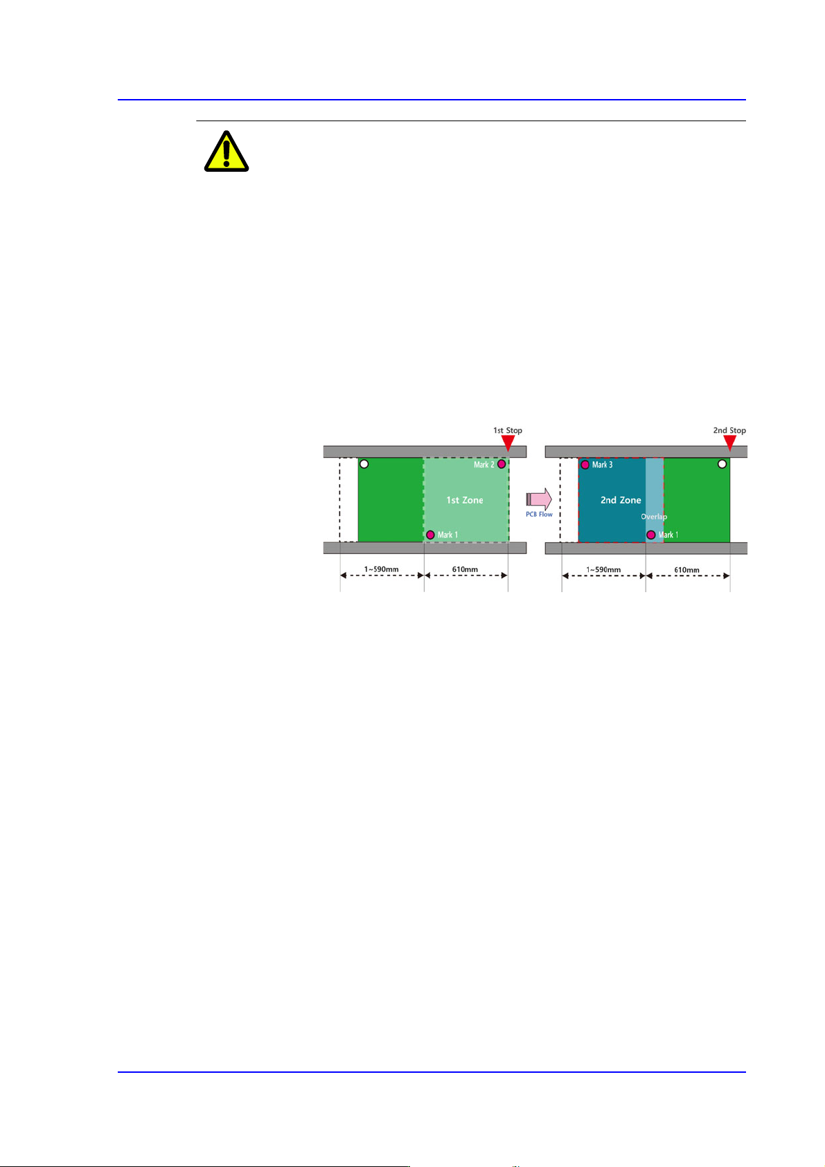
Caution Restrictions Related to Long PCB Production (Conditions of
the PCB for Two-level Placement)
In this equipment, the two-level placement is only available
for single conveyors with a length of 1,200mm, and a PCB
is defined as a long PCB when its length is between 610 ~
1,200mm.
In order to place parts on a long PCB, parts must be placed
in two steps by dividing the corresponding PCB into two
placement areas.
Also, at least two fiducial marks must exist in each
placement area and at least one fiducial mark must exist at
the location where the two areas intersect.
If Array / Block / Bad / Accept / Model marks are used for a
long PCB, the machine may not place parts on the
corresponding PCB according to the PCB condition.
Therefore, the user must understand the restrictions related
to the long PCB.
For reference, the figures used in the following cases are all
based on the PCB flow of the conveyor going from ‘Left ->
Right’.