SM482PLUS_Admin(Eng_Ver2.8).pdf - 第384页
14-12 Multi-Functional Placer SM482( L) PLUS Administrator’s Guide of the pixel for the certain area (test box) that is set using the fly camera. When the binary value of the pixel for the ar e a that is used to check wh…
14-11
Machine Calibration
Count X / Count Y
The size of the test box in the X-direction is called ‘Count X’ and the size in the Y-
direction is called ‘Count Y’.
Light
When examining the existence of the nozzle through the fly-camera, the lighting is the
decisive factor in determining the binary value of the pixel in the test box area.
Therefore, the area for examining whether the lighting system has a problem or not
must be set up in order to check any problem with the lighting conditions when
checking the existence of the nozzle through the fly-camera. At this time, insert the
biggest nozzle in the nozzle-holder to examine if the nozzle interferes with the area to
be checked.
This area is displayed in rectangular box shape in the vision screen.
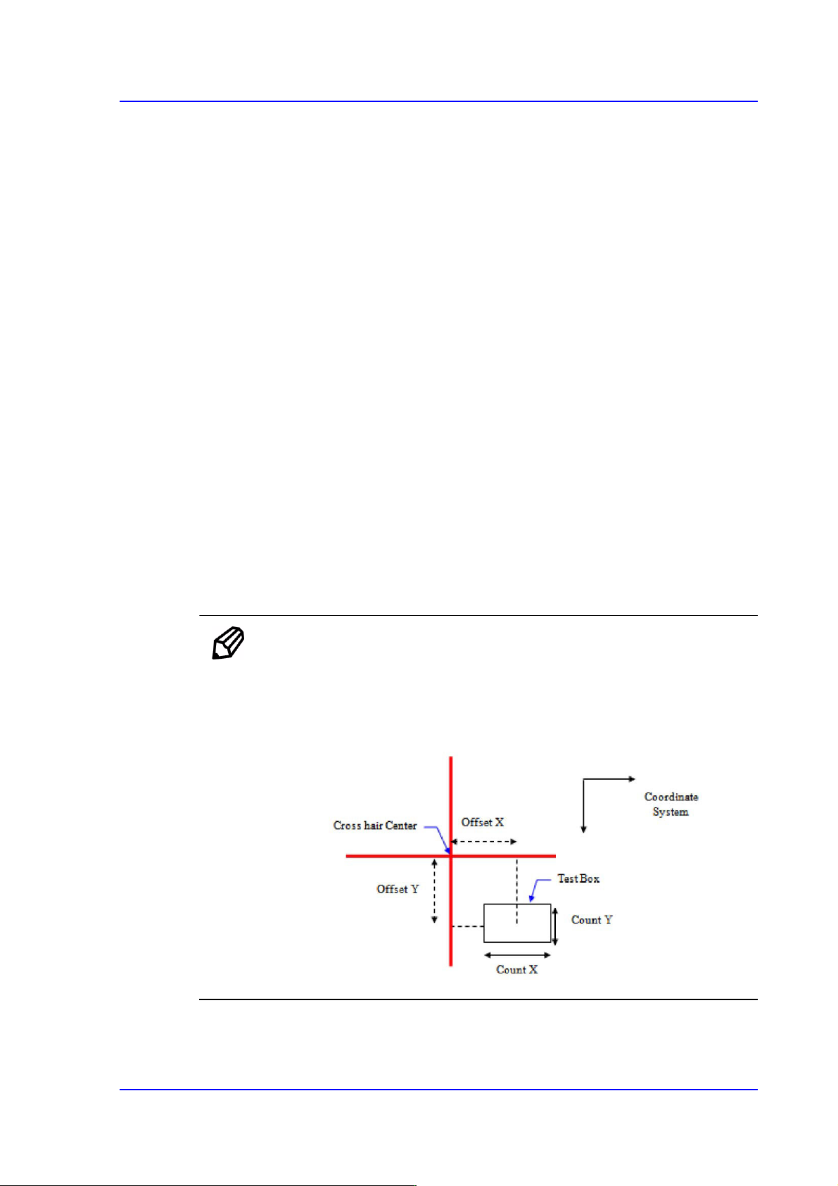
Offset X / Offset Y
When the distance from the cross hair center to this rectangular box (i.e. center of
the test box) in the vision screen is indicated in the Right-Down coordinate
system, the distance in the X-direction is called ‘Offset X’ and the distance in the
Y-direction is called ‘Offset Y’.
Count X / Count Y
The size of the test box in the X-direction is called ‘Count X’ and the size in the
Y-direction is called ‘Count Y’.
Memo When activating the <Test> button, the Offset or Count cell must be
clicked.
The coordinate system in the following figure is obtained from the
cross hair center of the vision screen.
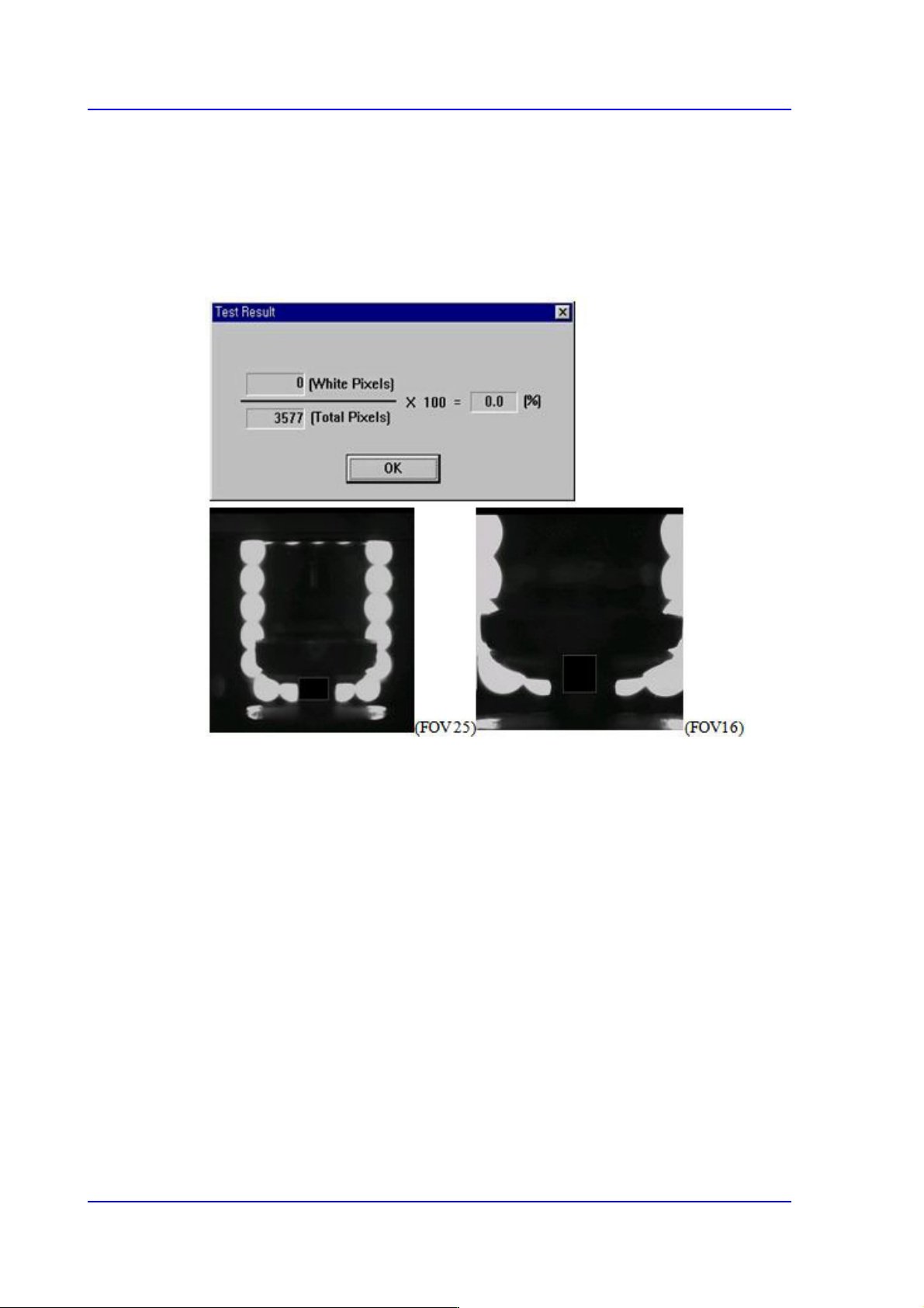
<Test> button
Sets the nozzle recognition condition and lighting condition by testing the binary value
14-12
Multi-Functional Placer SM482(L) PLUS Administrator’s Guide
of the pixel for the certain area (test box) that is set using the fly camera.
When the binary value of the pixel for the area that is used to check whether the nozzle
is mounted or not is below 30%, the nozzle is considered to be mounted. If the value is
above 30%, the nozzle is not considered to be mounted. If a nozzle actually exists, the
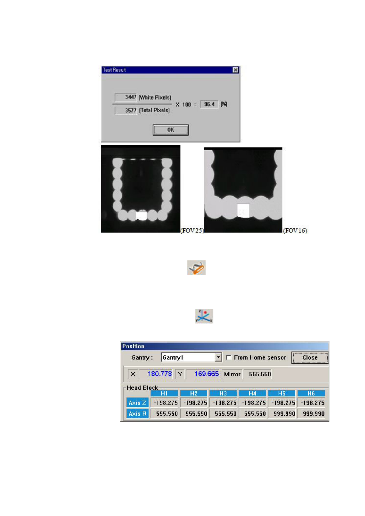
value must be close to ‘0’, if a nozzle does not exist, the values must be close to ‘100’.
<When the nozzle is mounted on the head>
14-13
Machine Calibration
<When the nozzle is not mounted on the head>
<Manual Tools> button
Clicking this button will execute the “Manual Control” dialog box by performing the
same function as selected by the in the View menu.
Head Mirror Teaching
The default value is 18. Can be different according to the system.
1) Select the Current Position( ) in the View menu to execute the
“Position” dialog box.