SM482PLUS_Admin(Eng_Ver2.8).pdf - 第490页
15-36 Multi-Functional Placer SM482( L) PLUS Administrator’s Guide Ref. The test result value must be with in ±10 from the fo llowing reference value. Side Outer Coaxial 00 0 0 11 2 2 0 1 7 22 4 3 5 3 1 34 0 5 0 4 5 45 8…
15-35
System Setup
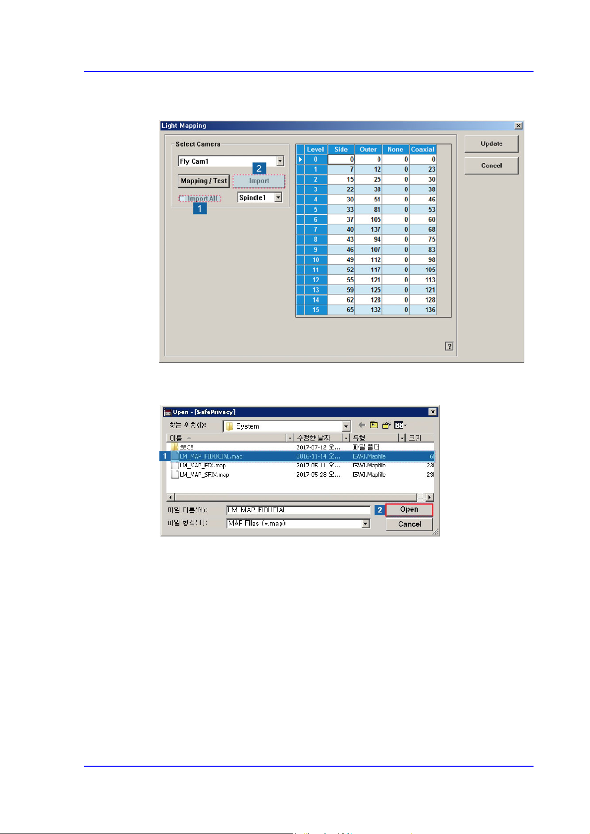
6. Check the <Import All> check box in the <Select Camera> group and click the
<Import> button.
7. Select the LM_MAP_FIDUCIAL in the <Open> dialog box and click the <Open>
button.
15-36
Multi-Functional Placer SM482(L) PLUS Administrator’s Guide
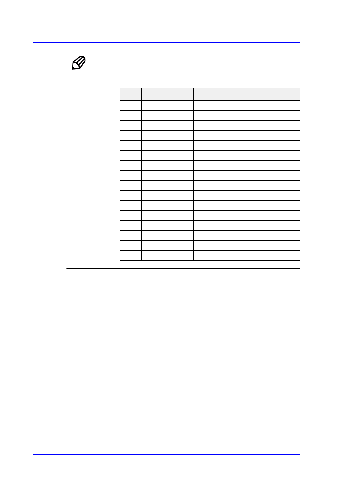
Ref. The test result value must be within ±10 from the following reference
value.
Side Outer Coaxial
00 0 0
112 20 17
224 35 31
340 50 45
458 65 60
576 80 74
694 100 94
7 110 120 113
8 122 140 133
9 134 170 140
10 146 190 140
11 158 200 140
12 168 210 140
13 178 220 140
14 188 240 140
15 188 254 140
15-37
System Setup
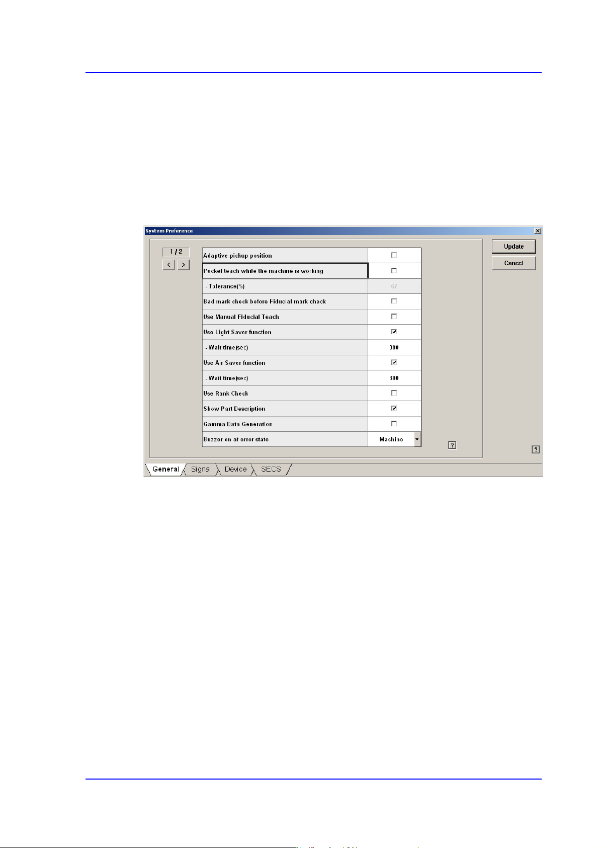
15.5. Pref. [F10]
Sets various options needed for equipment operation. When this button is clicked on, the
following dialog box is displayed.
15.5.1. <General> tab dialog
Sets general items related to the equipment operation.
Figure15.16 “General” tab dialog
<Adaptive pickup position> check box
If this check box is selected, when the equipment stops due to pickup error, the
coordinate calibrated to the pickup point of the corresponding feeder is reflected when
restarting the work.
The offset between the center of the part recognized through the vision system and the
center of the head that performed pickup is reflected automatically.
If this check box is selected, the edit box of the selected items is enabled right below it.
This edit box is used to adjust the tolerance when performing synchronized pickup.
At this time, the tolerance for the synchronized pickup is as follows:
Tolerance for synchronized pickup =Sync Pickup Tol +[Sync Pickup Tol X (a /100 )]
Sync Pickup Tolerance is that of the common data for the corresponding part.
'a' is the value entered into the edit box.