SM482PLUS_Admin(Eng_Ver2.8).pdf - 第453页
14-81 Machine Calibration 14.3.8. Board Positon Calibration T each the stopper position in the conveyor instal lati on area and the X position of the sensor . The following is the board position calibration procedure. 1.…
14-80
Multi-Functional Placer SM482(L) PLUS Administrator’s Guide
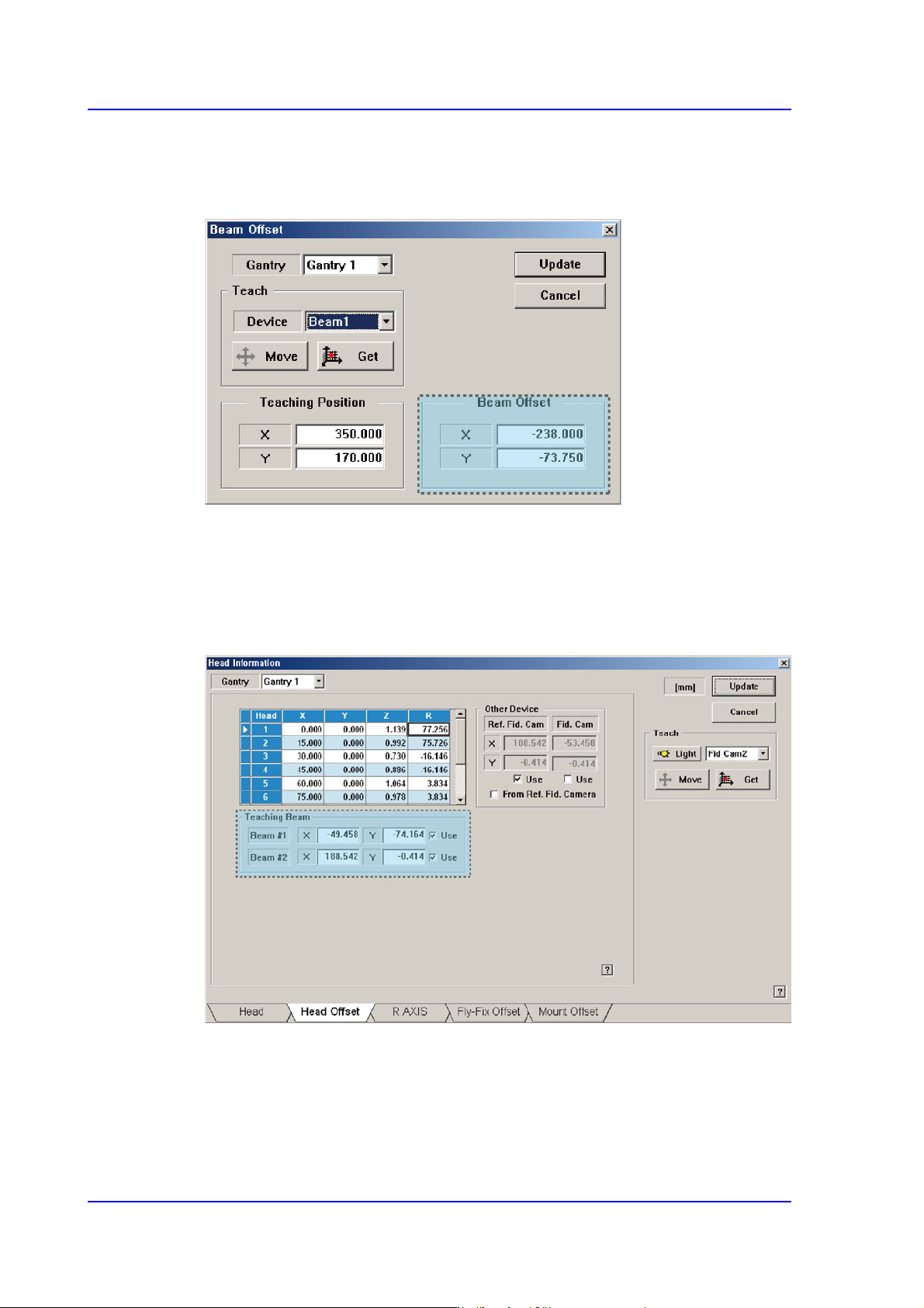
5. Select Beam 1 (or Beam 2) as a teaching tool and move it to the <Teaching Position>
using the jog box.
6. Press the <Get> button to save the current position in the <Beam Position>.
7. Select Gantry 2 in the <Gantry> combo box and perform calibration in the same
manner as was done for Gantry 1.
8. Press the <Update> button to save the setups.
9. You can check the result value in the Head Offset dislog box of the System Setup
menu.
14-81
Machine Calibration
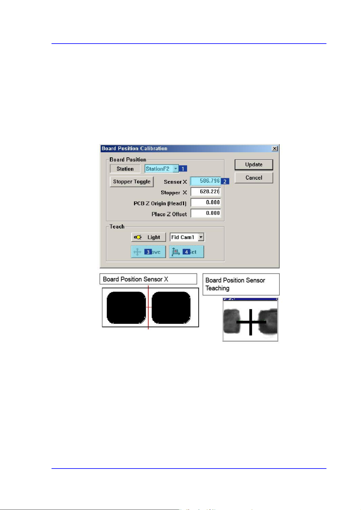
14.3.8. Board Positon Calibration
Teach the stopper position in the conveyor installation area and the X position of the
sensor.
The following is the board position calibration procedure.
1. Select the < Sensor X> edit box using the mouse and move the Fiducial Camera to the
position of Sensor X by clicking the <Move> button.
2. Perform teaching of the exact position using the teaching box. Enter the precise
coordinates for ‘Sensor X’ by pressing the <Get> button of the teaching box.
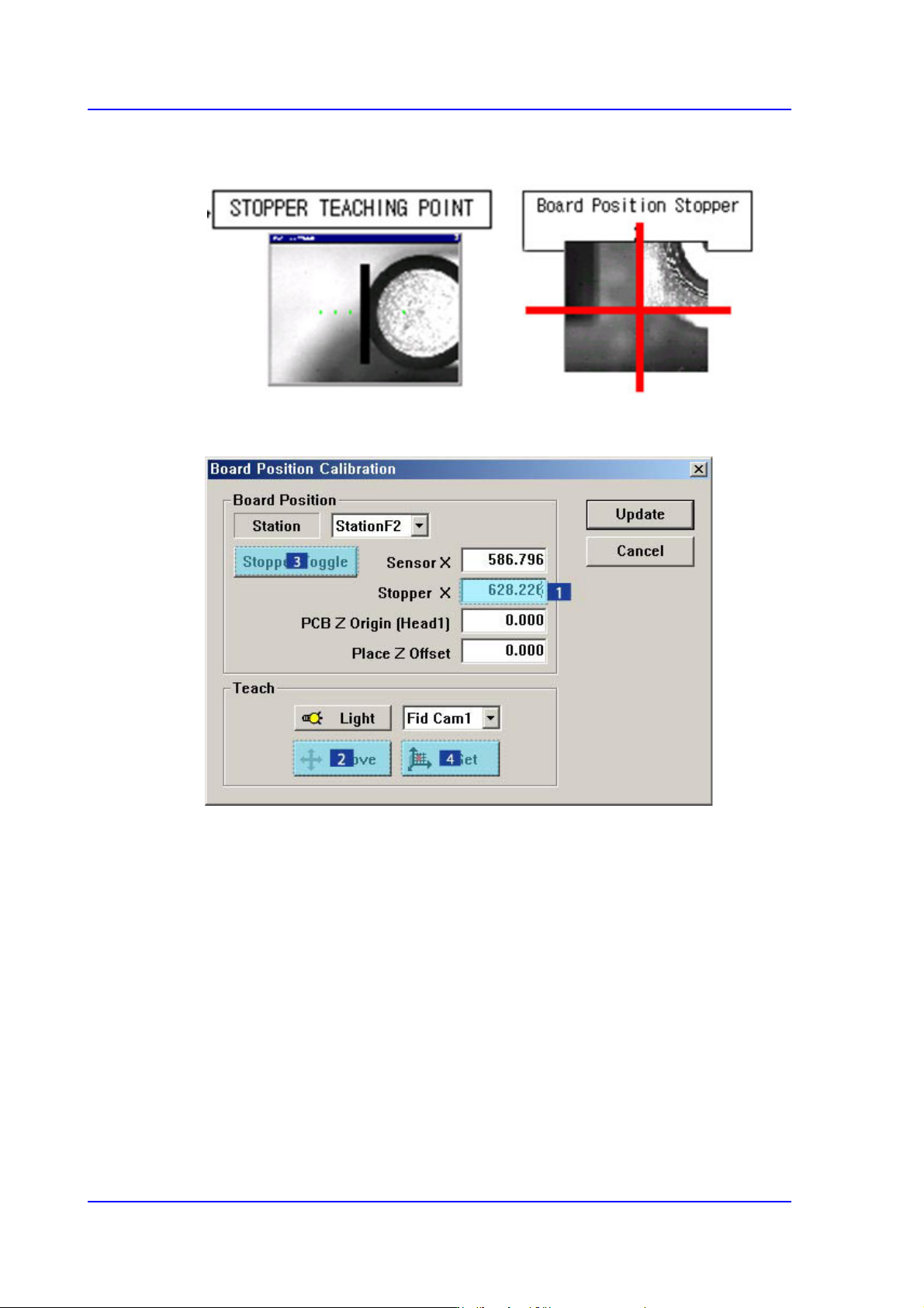
3. Select the < Stopper X> edit box using the mouse and move the Fiducial Camera to the
position of Stopper X by clicking the <Move> button.
4. Click the <Stopper Toggle> button in the left of the <Stopper X> edit box first to move
the stopper up and then teach the stopper position correctly using the teaching box.
5. Click the <Get> button to enter the coordinates in the <Stopper X> edit box.
14-82
Multi-Functional Placer SM482(L) PLUS Administrator’s Guide
6. Click the <Stopper Toggle> button to move down the stopper.
7. Save the data by clicking the <Update> button.