SM482PLUS_Admin(Eng_Ver2.8).pdf - 第501页
15-47 System Setup in an appropriate state to proceed with calibration. Displays a warning message if the user accesses the calibration me nu less th an 90 minutes afte r equipment bootup. <Use File Backup> Butto…
15-46
Multi-Functional Placer SM482(L) PLUS Administrator’s Guide
<Use Pickup Offset Sync> Check Box
When you modify the variable value of the part, the modified variable value of the part
will be automatically saved to the UPD.
<Use Multi-Vendor> check box
Refers to the function used to produce PCBs by using parts made by several
manufacturers for a part.
If a PCB program is created by registering a sub part for one part for one part in the
TOLP of the T-Solution, allows the work to be performed by using sub parts when
placing a part on the PCB with this check box being selected.
<Use NewPartEditor> check box
Selecting this check box will execute the NPE (New Part Editor) while editing a part.
<Use Coaxial Light Sync> Check Box
Sets whether to use the coaxial light synchronization function.
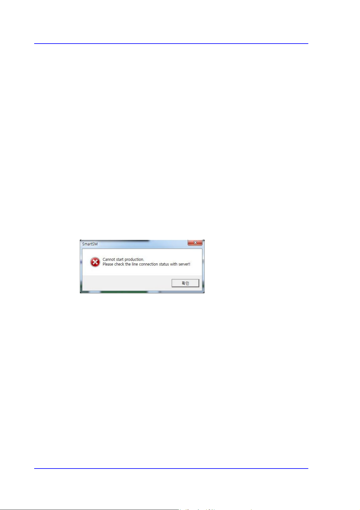
<PNP Connection Check> check box
Checks whether the machine and PNP are connected before starting production.
Starting production with the machine not connected to the PNP will display an error
message.
<PNP Barcode Interlock> Check Box
If this check box is selected, production will begin after determining the validity of the
PCB before production. This is a function that makes the equipment produce only the
permitted PCBs by transmitting the 2D barcode information to PNP - MES after the
2D barcode on the top surface of the PCB has been read before production when the
board has been fed to the equipment.
However, this function is only supported for the equipment loaded with the MES and
installed with the PNP from Hanwha.
<Use Auto Error Report> Button
Used to back up the MMI file manually when the user shuts the machine down. The
user can back up the MMI file manually only when the machine is in an idle state.
<Use iTAC> Button
Sets whether to use the iTAC program, which is a part of the external MES system.
<Use Calibration Guide> Button
If this check box is selected, the equipment notifies the user whether the equipment is

15-47
System Setup
in an appropriate state to proceed with calibration. Displays a warning message if the
user accesses the calibration menu less than 90 minutes after equipment bootup.
<Use File Backup> Button
If this check box is selected, the equipment saves the settings and other relevant files
including the system files of the equipment when the equipment is being shut down.
The files will be saved in a compressed format at the location designated by the user.
<Ignore Restriction Pitch> Button
If this check box is selected, the validation check for the pitch that varies depending on
the size of the part will not be performed during cycle check. Select this option if the
parts are being fed at a pitch different from the default pitch registered with the system
depending on the size of the parts being fed.
<Use Place Recovery> Button
If this check box is selected, a screen is displayed for the user to be able to place the
part again at the applicable location if the part is determined to have been misplaced
during production. However, this option configures the equipment to continue
production if the part has actually been placed correctly but determined to have been
misplaced by the equipment.
<Auto Apply Pick Up Height> Button
If this option is selected, the equipment uses part data to automatically set the pick up
height for the part. Automatically enters the sum of the part thickness and Z-position
of the tape feeder when a part is picked up by the tape feeder.
Use: Automatically enters the automatically applied pick up height (Z-value) of
the part in the feeder window and the part is actually picked up based on the value
entered.
Use (No display): Does not automatically enter the automatically applied pick up
height (Z-value) of the part in the feeder window but the part is actually picked up
based on the value entered.
<Use RESCUING> Button
If this check box is selected, <Enable RESCUING> check box in the <Option Setting>
group under the <Product> menu is enabled. For details on this function, refer to
“12.1.2. Option Setting”.
<Update> button
Transmits the change data to the equipment and closes the dialog box.
15-48
Multi-Functional Placer SM482(L) PLUS Administrator’s Guide
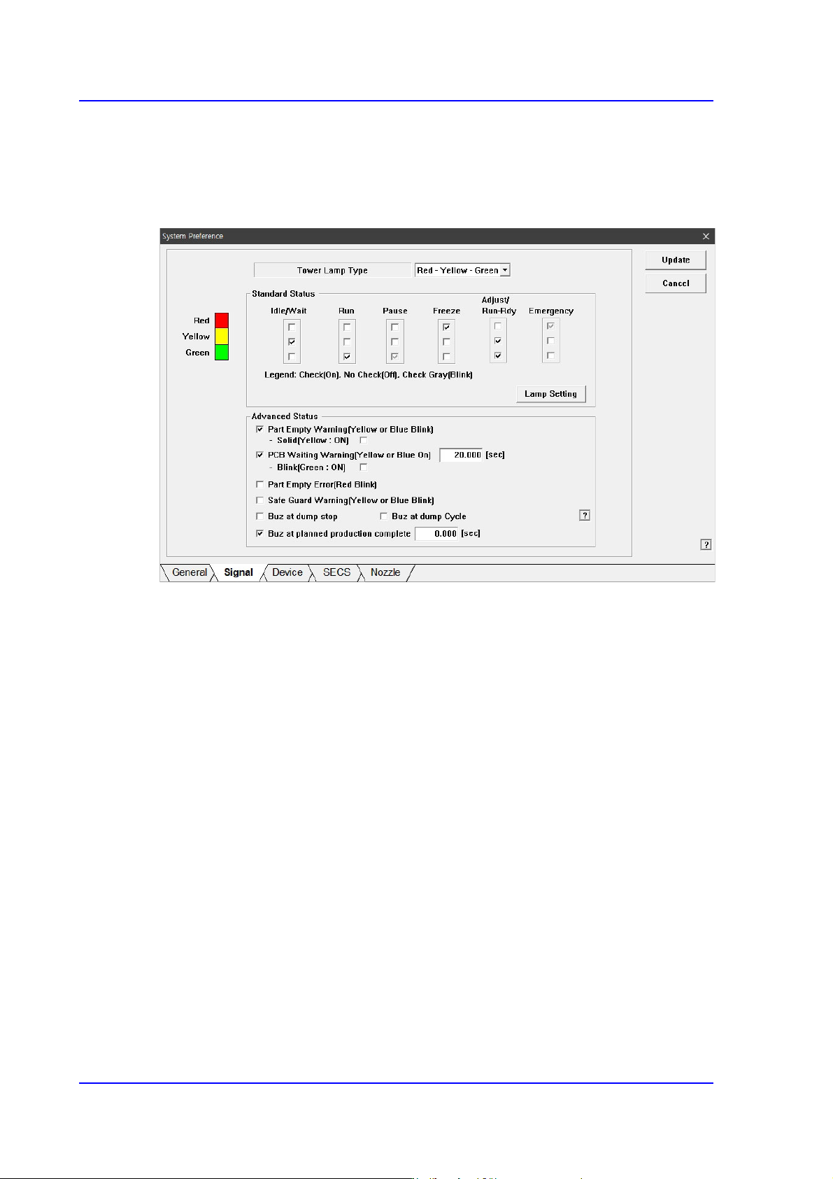
15.5.2. <Signal> tab dialog
Set the status of the signal light. When this button is selected, the following screen is
displayed.
Figure15.17 “Signal” tab dialog
<Tower Lamp Type> combo box
Select the signal tower type. Available types are as follows.
Red –Yellow –Green: When the signal light consists of “Red –Yellow –Green”.
Red –Blue –Green: When the signal light consists of “Red –Blue –Green”.
<Standard Status> group
Set the status of the signal light corresponding to the equipment status.
For example, if you want to turn on the “Yellow” lamp of the signal tower in the idle/
wait status, check the corresponding “Yellow” lamp check box among the 3 check
boxes under the Idle/Wait.
The status and meanings of the check boxes are as follows.
Checked: Turns on the corresponding lamp.
Not checked: Turns off the corresponding lamp.
Checked in gray: Flickers the corresponding lamp.