SM482PLUS_Admin(Eng_Ver2.8).pdf - 第285页
8-33 Feeder Setup <T ray Size> Caption box The size of the tray . This means the s i ze excluding the indivi dual width of the side of the pallet. <Slave width> Caption box It means the wing width on the …
8-32
Multi-Functional Placer SM482(L) PLUS Administrator’s Guide
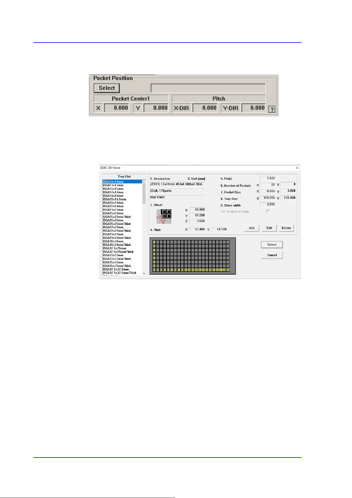
<Use JEDEC DB>
This function facilitates teaching using JEDEC DB.
<Select> button
This brings up the information on the tray that will be worked on from the
JEDEC tray DB.
Selecting this button will launch the <JEDEC DB Viewer> dialog box.
<Description> Caption box
The style and size of the tray.
< Offset> Caption box
It means offset value of X, Y, Z.
<Pitch> Caption box
The distance between the centers of the parts in the pallet.
<PickZ> Caption box
Sets the height of the Z axis when picking up parts supplied from the
pallet.
<Number of Pockets> Caption box
The number of pockets in the palette.
<Pocket Size> Caption box
Pocket size of the tray.
8-33
Feeder Setup
<Tray Size> Caption box
The size of the tray. This means the size excluding the individual width of
the side of the pallet.
<Slave width> Caption box
It means the wing width on the side of the pallet.
<Seated on Body> Caption box
This function is not supported by this equipment.
<Add> button
It is a function to generate new JEDEC Tray.
<Edit> button
This is a function that can modify existing JEDEC Tray defined.
<Delete> button
This function allows you to delete an existing defined JEDEC Tray.
<Pocket Center1 > Caption Box
Indicates offset of X plus slave width.
<Pitch> Caption box
Indicates the X, Y Pitch value.
<Set Array> button
(For array PCBs) Sets the offset value between the home position of the small PCB in
each array PCB and the placement home position of the array PCB.
<Unit> group
Select the tray unit to edit.
Button selects the previous unit, Button selects the next unit.
<Unit Type> caption box
Displays the type of selected tray unit. The type of the corresponding tray unit should
be set in the system.
<Use 2 Tray> check box
Check this check box when using 2 trays on a pallet. This function is not applied to
this machine.
<Teach> group
Used for moving the selected object to the assigned position of coordinates by rotating
XY axis driving motor, or for obtaining the present coordinates of the selected object.

8-34
Multi-Functional Placer SM482(L) PLUS Administrator’s Guide
Button
Setup illumination of fiducial camera to be used for teaching. Please refer to
“8.1.2 Stick Unit” for more information.
Combo Box
Used for selecting the object to move to the designated coordinates by rotating the
XY axis driving motor or to select the object for which the present coordinates is
searching. Selectable objects are as follows:
Fid Cam: Selects the fiducial camera of the head.
Head 1 ~ Head 6: Selects the Head #1~Head #6
Beam1: Beam1 can be selected from machines to which a Height Sensor is
applied. It is used for automatic measurement of the Z-axis height.
<Move> button
Move the object selected in the Combo Box to the position of the assigned
coordinates. Before executing <Move> button, the cell in the grid (Coordinates for
pickup point of tray feeder) corresponding to the desired position must be clicked
on.
<Get> button
Obtain coordinates for XY axis with reference to the object selected in the Combo
Box. At this time, Before executing <Get> button, the cell in the grid (Coordinates
for pickup point of tray feeder) corresponding to the desired position must be
clicked on.
<Shuttle Supply> button
In case of the shuttle tray feeder, the component is fed to the shuttle from the tray
feeder, and it moves the component to the pickup position.
<Pallet Out > button
Loads the pallet to be ready for placement from the elevator of the tray feeder. This
function is applied to the automatic tray feeder.
<Pallet In > button
Release the pallet to be finished placement from the elevator of the tray feeder. This
function is applied to the automatic tray feeder.
<Z Teach> button
Measures the Z axis height for the pickup point of feeder automatically using
pneumatic pressure. Insert the CN040 nozzle into the nozzle holder of the head and
select the pallet for which Z axis height is to be measured from the <Grid> group and
then click the <Move> button.