SM482PLUS_Admin(Eng_Ver2.8).pdf - 第427页
14-55 Machine Calibration Since the position at which the Z of fset is measured deviates from the calibration tool position (center) by 3mm, if any foreign mate rial on the calibrati on tool is present, remove it. 3. In …
14-54
Multi-Functional Placer SM482(L) PLUS Administrator’s Guide
6. If the calibration procedure is completed properly, the result as shown in the following
figure is displayed and then the message, “Move (Fiducial/Teach) Camera Offset is
Finished. Remove Tool Plate!” appears. At this point, remove the flat board calibration
tool placed on the Fix 1 Camera. Otherwise, damages may be caused by collision with
the head.
Memo The reference values for the calibration of the Camera Offset is as
follows.
Camera Offset (FOV 12)
Offset X : -76.0mm ~ -74.0mm
Offset Y : 54.0mm ~ -56.0mm
14.3.7.4. Head Z / R Offset Calibration
The distance from the upper surface of the PCB to the Z axis home is set mechanically. For
the Z offset calibration, measure the offset for this distance based on the upper surface of
the PCB by using pneumatic pressure.
For the R offset calibration, measure the offset of the angle to align the nozzle holder
based on zero (0) degrees.
The following is the process that the Z offset calibration is performed. The nozzle used for
calibration is the CN040 nozzle.
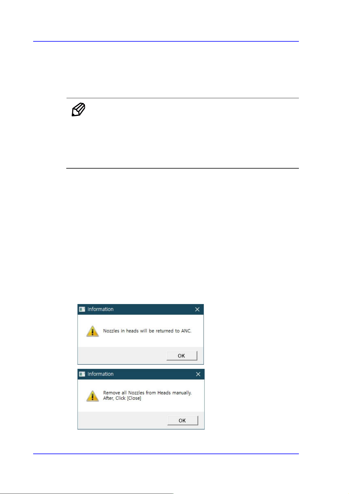
1. Click the <Head Z / R Axis Offset> button.
2. Click the <Nozzle Prepare> button and remove all nozzles inserted in the nozzle
holders of all heads. Insert the CN040 nozzle into the No. 14 hole of the ANC.
14-55
Machine Calibration
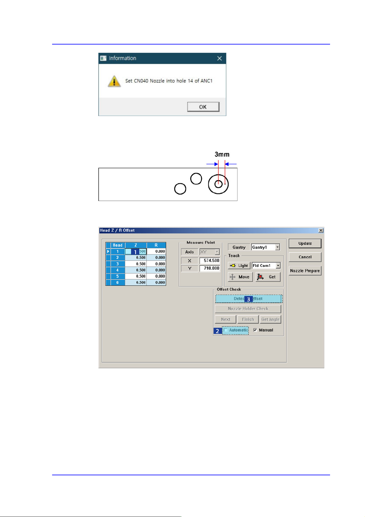
Since the position at which the Z offset is measured deviates from the calibration tool
position (center) by 3mm, if any foreign material on the calibration tool is present,
remove it.
3. In the <Grid> group, select the Z axis for which the calibration is to be performed and
click the <Detect Z Offset> button after selecting the <Automatic> check box.
4. Click the <Next> button.
5. The head moves to the designated position on the ANC automatically. Then the
machine creates pneumatic pressure and performs calibration while moving the
spindle down from Head 1 to Head 6 in order.
6. If the calibration is completed, the calibration result is reflected on the Z column of the
<Grid> group automatically.
14-56
Multi-Functional Placer SM482(L) PLUS Administrator’s Guide
7. Press <Update> button to apply the calibration result to the machine
Memo The reference values for the Z-offset are as follows.
Head1~ Head6 : -1.5 ~ 1.5 mm
If the Z offset value exceeds this range, it means that the head has a
serious problem. Therefore, check for the home location, spindle,
LM, and verify if the motor operates normally.
The following is the procedure to perform the ‘R-Offset Calibration’.
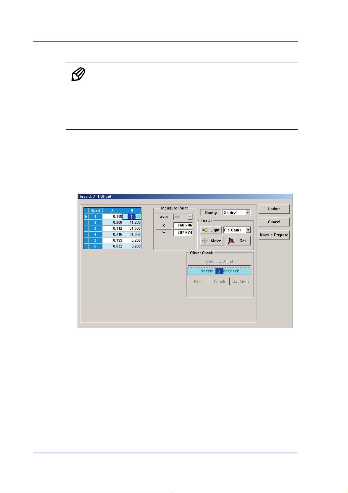
1. In the <Grid> area, input “0” for all R-axis values of the heads for which the
calibration is to be performed.
2. In the <Grid> group, select the R-axis for which the calibration is to be performed and
click the <Nozzle Holder Check> button. (Set value to head 1 by arbitrarily.)
3. Then a message reading, “First, We must Put all Nozzles from Heads manually. To
Moving Down Z Axis, Click [Next].” will be displayed in the message box. Click the
<Next> button to manually remove the nozzles attached to all heads.
At this time, for the ANC, the virtual nozzle CNT0 is set for the No. 1 hole of the ANC
and it is regarded that the corresponding head picked the CNT0 nozzle.