SM482PLUS_Admin(Eng_Ver2.8).pdf - 第29页
Preface xv The placement Speed The following data concerns the speed of placement for each part. The actual cycle time can vary depending on the size of PCB, frequency of the nozzle replacement, etc. The pick and place c…
Multi-Functional Placer SM482(L) PLUS Administrator’s Guide
xiv
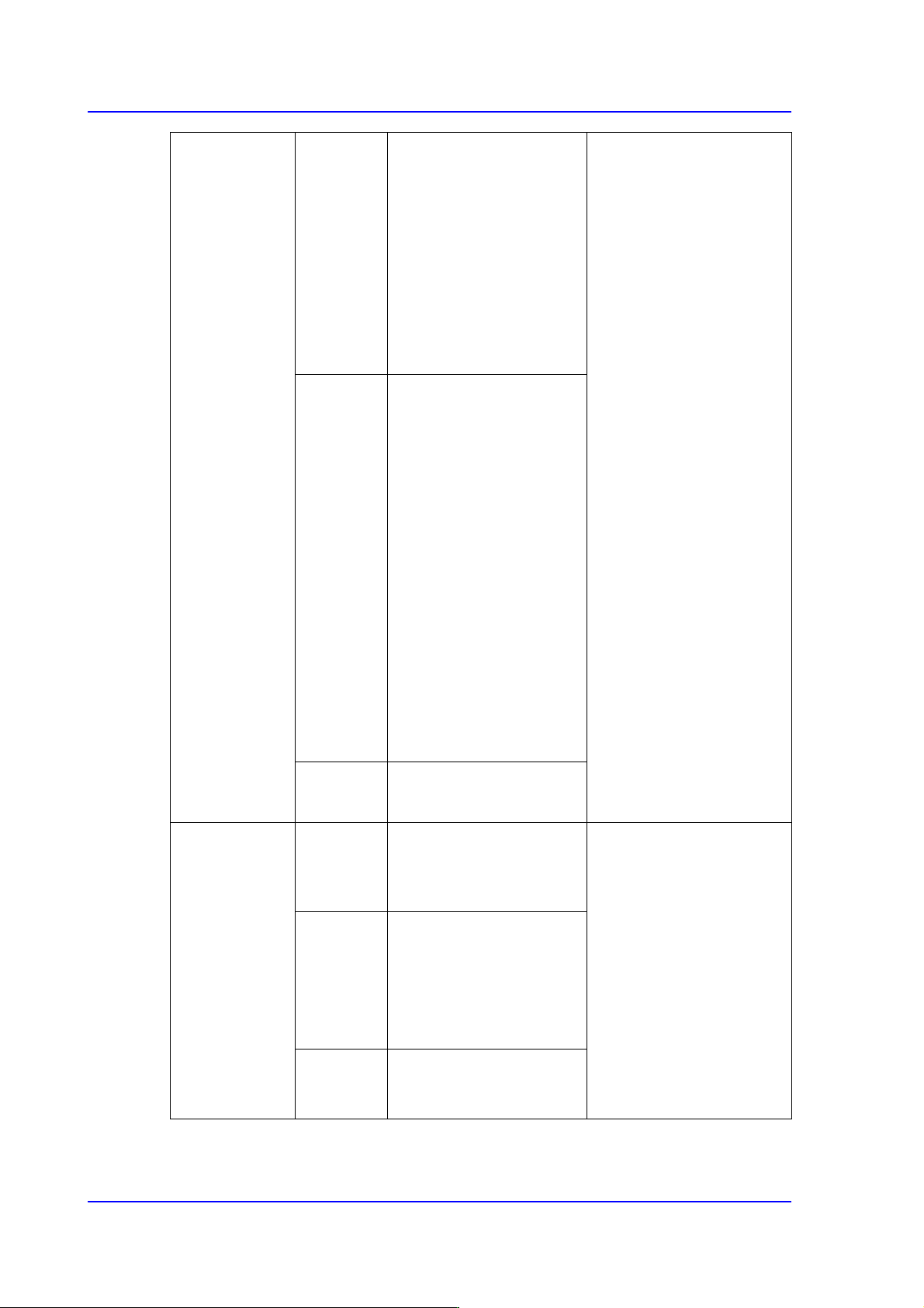
Upward vision
MEGA FOV 45
mm
IC,
Connector
Less than □16 mm,
Lead pitch: More than
0.3 mm
Less than □32 mm,
Lead pitch: More than
0.4 mm
Less than □42 mm,
Lead pitch: More than
0.5 mm
□42~□55mm:
Segmentation recognition
(Ball Dia. More than
0.5mm, Ball pitch More
than 1.0 mm, Lead pitch
More than 0.8 mm)
Connector diagonal
length 55~75mm:
Segmentation recognition
(Lead pitch More than 1.0
mm)
BGA, CSP
Less than □16 mm,
Ball Dia.: More than 0.2
mm,
Lead pitch: More than
0.4 mm
Less than □32 mm,
Ball Dia.: More than 0.25
mm,
Lead pitch: More than
0.5 mm
Less than □42 mm,
Ball Dia.: More than 0.4
mm,
Lead pitch: More than
1.0 mm
Maximum
Height
15 mm
Upward vision
FOV 35 mm
IC,
Connector
Less than □32 mm,
Lead pitch: More than
0.4 mm
□32~□42mm:
Segmentation recognition
(Ball Dia. More than
0.5mm, More than Ball
pitch 1.0 mm, More than
Lead pitch 0.5 mm)
□42~□55mm:
Segmentation recognition
(Ball Dia. More than
0.5mm, More than Ball
pitch 1.0 mm, More than
Lead pitch 0.65 mm)
BGA, CSP
Less than □32 mm,
Ball Dia.: More than
0.375 mm,
Lead pitch: More than
0.75 mm
Maximum
Height
15 mm
Preface
xv
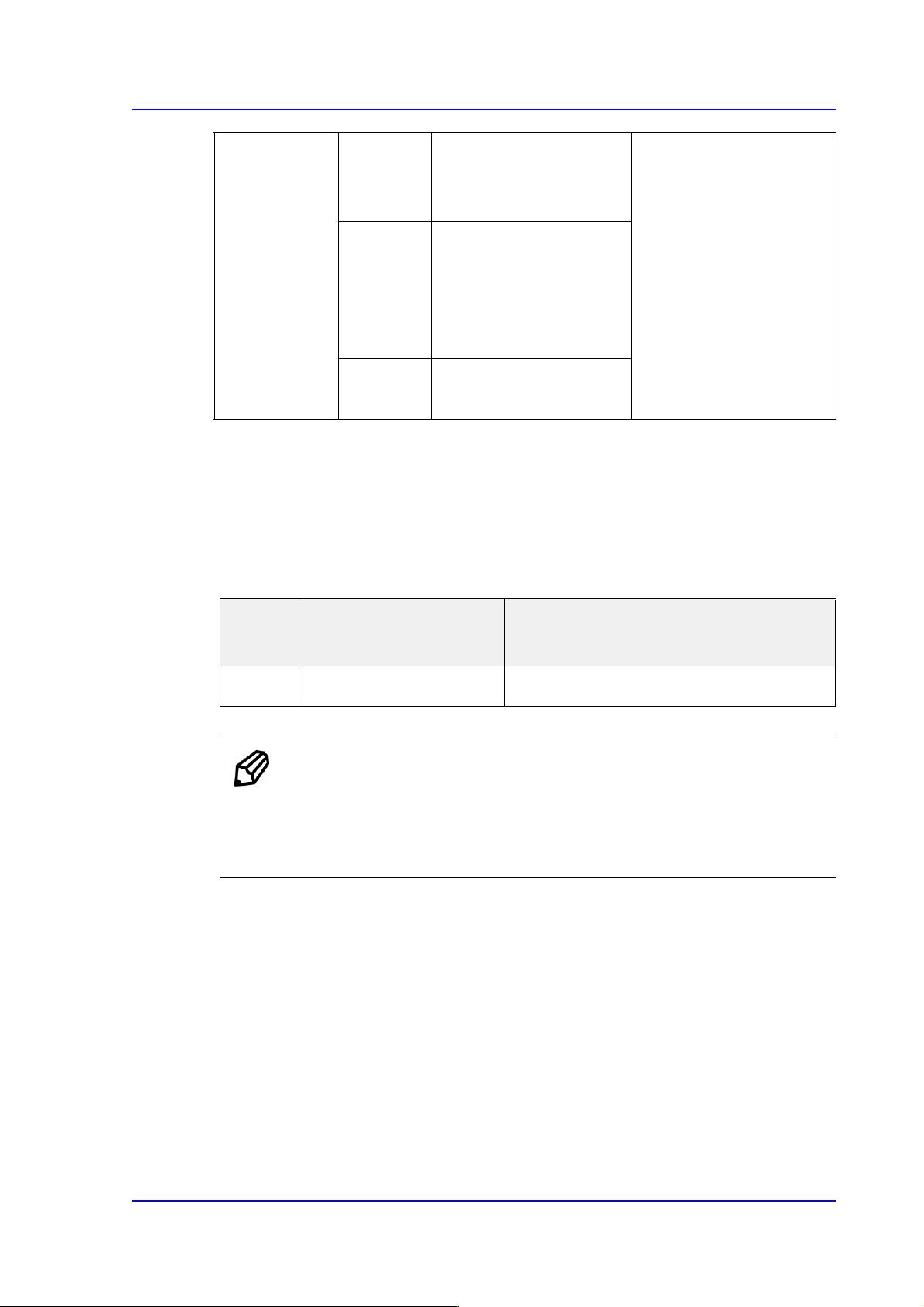
The placement Speed
The following data concerns the speed of placement for each part. The actual cycle time
can vary depending on the size of PCB, frequency of the nozzle replacement, etc.
The pick and place cycle time
Tablei.2The pick and place speed
Memo In actual placement, the conditions that determine the cycle time may
vary depending on many factors such as the type of components, size
of PCB, placement position, etc. For more detailed information,
please contact our business department or the local agent.
Upward vision
FOV 45 mm
IC,
Connector
Less than □42 mm,
Lead pitch: More than
0.5 mm
□42~□55mm:
Segmentation recognition
(Ball Dia. More than
0.5mm, Ball pitch More
than 1.0 mm, Lead pitch
More than 0.8 mm)
Connector diagonal
length 55~75mm:
Segmentation recognition
(Lead pitch More than 1.0
mm)
BGA, CSP
Less than □42 mm,
Ball Dia.: More than 0.4
mm,
Lead pitch: More than
1.0 mm
Maximum
Height
15 mm
Classifi
cation
Speed Remarks
Chip
30,000 CPH(1608)
Simultaneous Pickup Standard Fly Vision
Multi-Functional Placer SM482(L) PLUS Administrator’s Guide
xvi
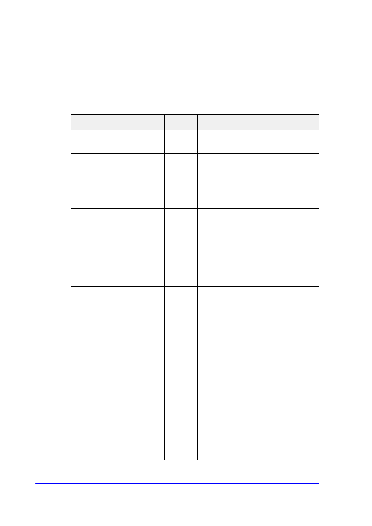
Placement Accuracy
The placement precision for applicable components type is shown in the following table,
and is applicable to general components usage as well.
The degree of placement may be different according to the composition of options for the
camera used for recognition of parts.
Classification XY R Cpk Remarks
Chip 0402 ± 0.04
mm
± 5.00 ° 1.0 Flying Vision MEGA FOV16
mm, Mount Offset
Chip 0603 ± 0.08
mm
± 5.00 ° 1.0 Flying Vision(Mega-
FOV25mm, Non-Mega-
FOV16mm)
Chip 1005 ± 0.10
mm
± 5.00 ° 1.0 Flying Vision(FOV16mm,
FOV25mm)
QFP100 0.5 P ± 0.06
mm
± 0.25 ° 1.0 Flying Vision(FOV25mm),
Upward Vision(FOV35mm,
FOV45mm)
QFP168 0.3 P ± 0.03
mm
± 0.20 ° 1.0 Upward Vision(Mega-
FOV35mm)
QFP256 0.4 P ± 0.05
mm
± 0.10 ° 1.0 Upward Vision(Mega-
FOV35mm, Mega-FOV45mm)
QFP304 0.5 P ± 0.06
mm
± 0.10 ° 1.0 Upward Vision(Mega-
FOV35mm(4 divisions),
FOV45mm)
BGA256 1.0 P ± 0.10
mm
± 0.40 ° 1.0 Flying Vision(FOV25mm),
Upward Vision(FOV35mm,
FOV45mm)
BGA □12 0.5 P
± 0.06
mm
± 0.30 ° 1.0 Upward Vision(Mega-
FOV35mm, Mega-FOV45mm)
BGA □17 0.75 P
± 0.10
mm
± 0.40 ° 1.0 Flying Vision(FOV25mm),
Upward Vision(FOV35mm,
FOV45mm)
BGA □52 1.27 P
± 0.10
mm
± 0.30 ° 1.0 Upward Vision(Mega-
FOV35mm(4 divisions),
FOV45mm)
Connector 75 mm
1.27 P
± 0.18
mm
± 0.25 ° 1.0 Upward Vision(Mega-
FOV45mm(2 divisions)