SM482PLUS_Admin(Eng_Ver2.8).pdf - 第251页
7-79 Part Registration Pre Flux Selected in cases to dips a part into flux after recognizing it. <Flux Depth> edit box Selects the depth of part d ipping into flux. Set the d epth based on '0' accord …
7-78
SM PLUS Administrator’s Guide
<X Offset> edit box
It is possible to set the X offset.
<Y Offset> edit box
It is possible to set the Y offset.
<Z Offset> edit box
It is possible to set the Z offset.
<R (Place Angle> edit box
It is possible to set the R offset.
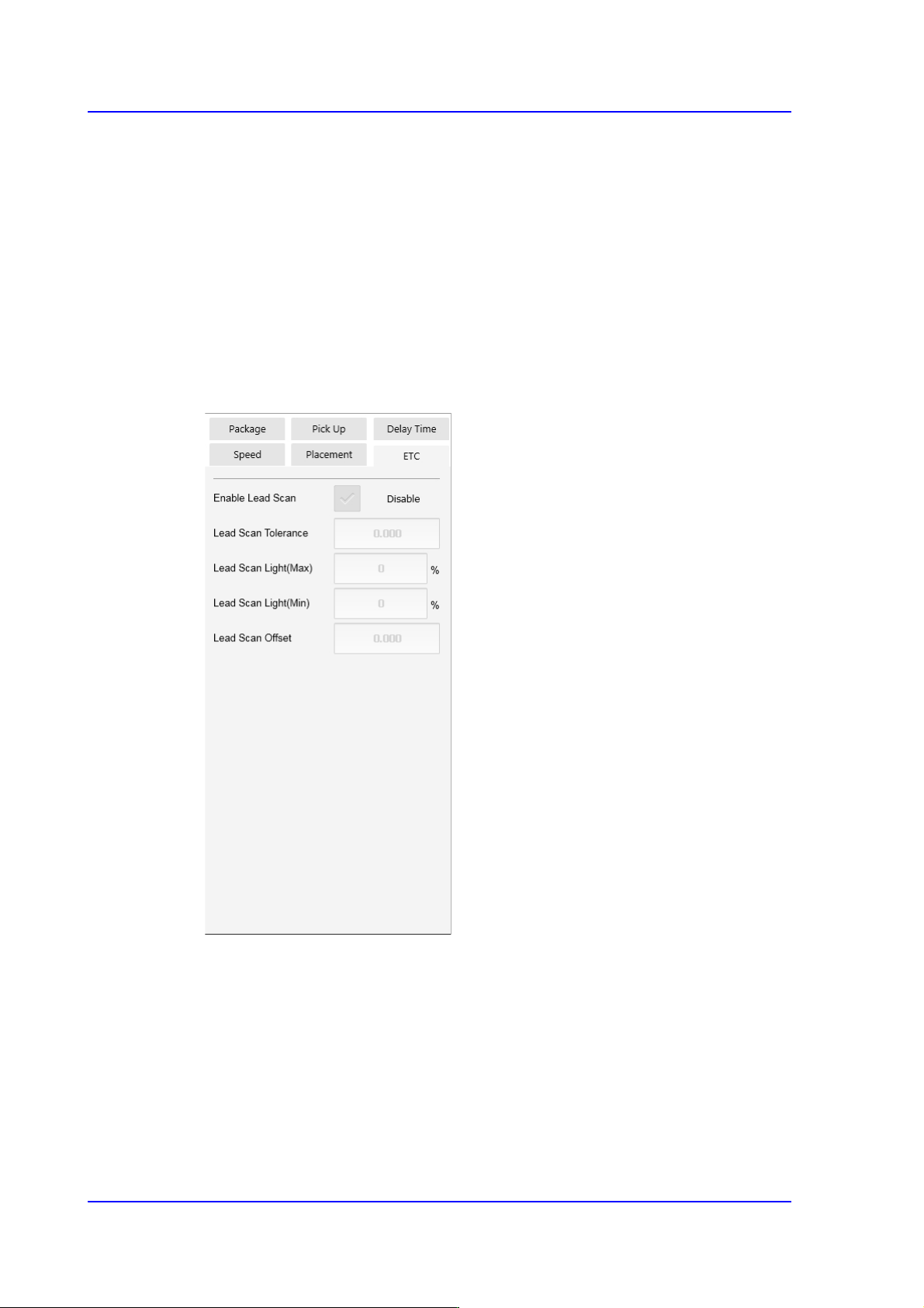
<ETC> tab
<Flux Type> selection box
Selects the method for flux part recognition. This function can be used for the
machine equipped with a flux device.
No Flux
Selected when the part is not a flux part. If this option is selected, the POP
function cannot be used.
Post Flux
Selected in cases to recognizes a part after dipping it into flux.

7-79
Part Registration
Pre Flux
Selected in cases to dips a part into flux after recognizing it.
<Flux Depth> edit box
Selects the depth of part dipping into flux. Set the depth based on '0' according to
the properties of the part.
<Flux Thickness> edit box
Input the thickness of the flux film formed on the table.
<Flux Dipping Time> edit box
Input the period of time during which a part remains dipped in flux. The default
value is 0.2000 and its range is 0.1000~5.000.
<Flux Dipping Inspect> check box
Recognizes the shape of flux applied on the balls of BGA parts.
<Flux Min Ratio(%)> edit box
Sets the ratio of the minimum allowable area of flux recognized by the Vision
against the ball area.
<Flux Max Ratio(%)> edit box
Sets the ratio of the maximum allowable area of flux recognized by the Vision
against the ball area.
<Flux Brightness> edit box
Sets the brightness of flux recognized by the Vision.
<Enable lead scan> check button
Selected when inspecting the leads of an IC part. This function can be used only
for machines equipped with a lead scanner.
<Lead Scan Tolerance> edit box
Input the value that allows the extent by which a lead deviates from the normal
pattern. It is indicated in mm. If the difference in the height of two neighboring
leads is greater than this value or a specific lead deviates from this value when it is
assumed that the inclination of each lead is straight line, the corresponding part is
judged to be defective.
<Lead Scan Gain> edit box
Sets the gain of the light receiving section for the laser spot beam. In general, set
this value to '2'.
<Lead Scan Offset> edit box
Even if it is possible to input and use an offset at the position calculated for lead
scanning, generally set it to '0'.

7-80
SM PLUS Administrator’s Guide
<Lead Scan Test> button
Performs a lead scan test.