SM482PLUS_Admin(Eng_Ver2.8).pdf - 第472页
15-18 Multi-Functional Placer SM482( L) PLUS Administrator’s Guide 15.4. Light Mapping Calibrate the brightness of the light for the ca mera. In order to perfo rm this cal ibration, insert the LightFly or LightFix into t…
15-17
System Setup
Set the second point correctly and press the ‘Enter’ key.
<Teach…[Z]> button
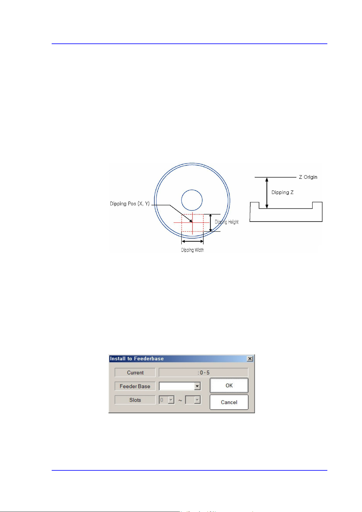
Teach the Z coordinate of the dripping position. The teaching procedure is as
follows:
Select the device to be taught first from <Device> in the <Teach> group and
insert the CN040 nozzle in the nozzle holder of the corresponding head.
Move the head to the dripping position.
Move down the spindle of the head until it contacts the disk surface. If the
nozzle end contacts with the disk surface, the change in the pneumatic
pressure occurs and the Z axis position is taught automatically.
<Use Flux Device> check box
This check box is selected to set the item related to the flux module.
<Churning> button
If this button is selected, the disk of the flux module rotates.
<Not Usable Lane> group
It sets the item related to the operation of the flux module.
<Feeder Base> button
Selects the feeder base on which the flux module is to be installed.
15-18
Multi-Functional Placer SM482(L) PLUS Administrator’s Guide
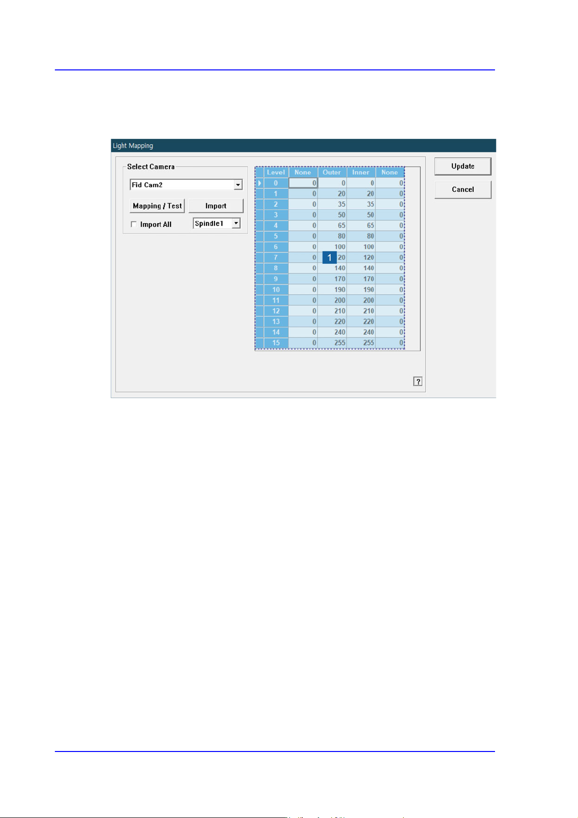
15.4. Light Mapping
Calibrate the brightness of the light for the camera. In order to perform this calibration,
insert the LightFly or LightFix into the No. 1 nozzle of the ANC.
1: Light Level
<Select Camera> combo box
Selection Control
Select the camera to perform light mapping.
Repeat this procedure for all fly cameras and fix cameras.
Light Level group
Sets the brightness by light level.
<Level> column
Dislays 16 steps of lighting.
<Side> / <Outer> / <Inner> column
The value within the range up to 255 for each light level is inputted.
For the Fly Camera
Input the side illumination value within the range of 256 values.
For the Fix Camera
Input the side illumination value within the range of 4096 values.
<Back1> / <Back2> column
Enabled only when the fix camera was selected. The value within the range up to
15-19
System Setup
4096 for each light level is inputted.
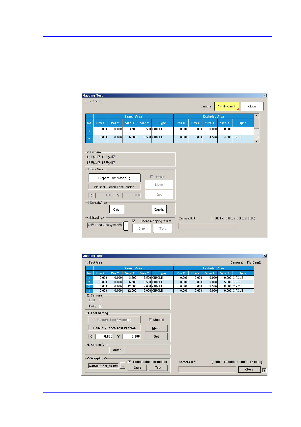
<Mapping/Test> button
Perform test or automatic mapping for the light level for the camera selected from the
<Select Camera> group.
Figure15.10 When the Fly Camera is selected
Figure15.11 When the Fid Camera is selected