SM482PLUS_Admin(Eng_Ver2.8).pdf - 第226页
7-54 SM PLUS Administrator’s Guide <Sampling level for body recogni tion> edit box Enabled when the <Use Edge Matching > check button is selected. Set the sampling accuracy when recognizin g the body . (0~1…
7-53
Part Registration
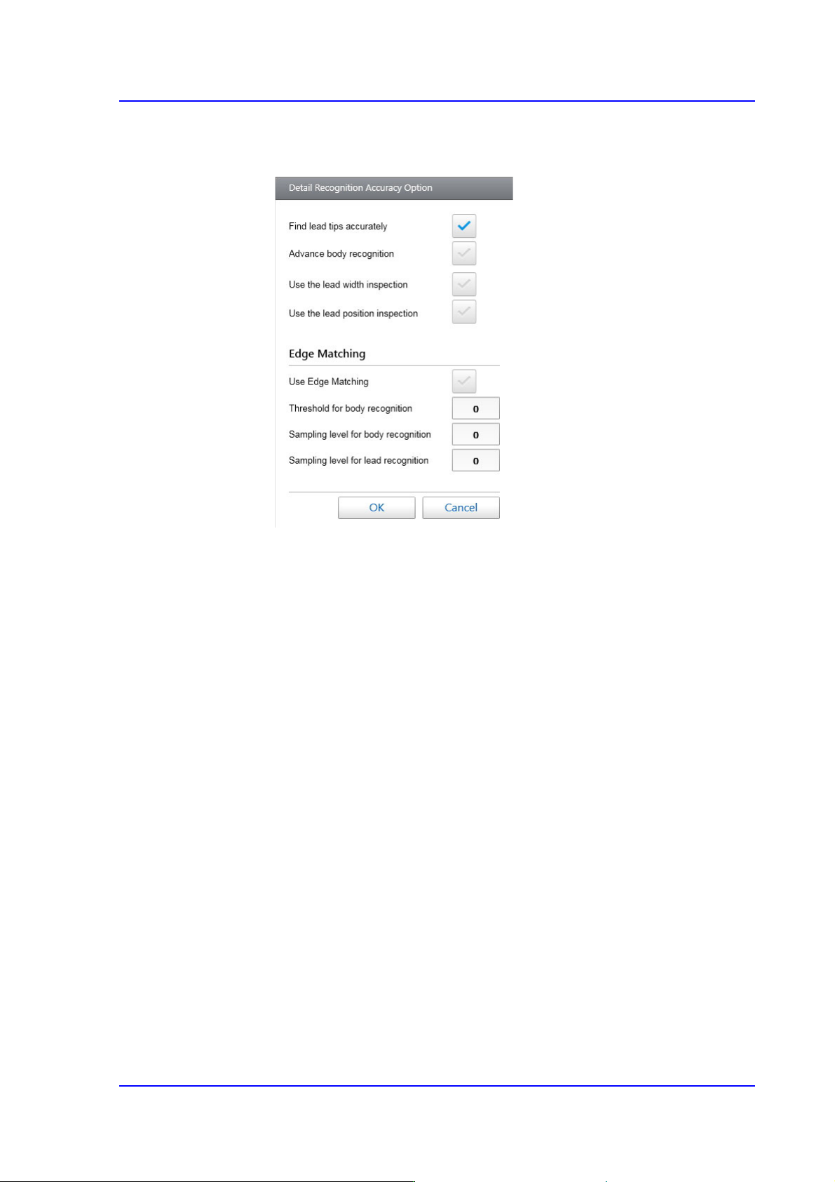
<Detail> button
Sets the detail parameters related to the recognition of IC parts.
<Find Lead Tips Accurately> check button
Selected in cases to used to recognize the lead end accurately. In the case
of the connector whose leads exist at SOP or only one direction with the
number of leads exceeding 8, checking this check button will increase the
recognition accuracy.
<Advance body recognition> check button
Selected in cases to calculates the approximate position of the part by
using the part body information when recognizing the part.
<Use the lead width inspection> check box
Inspects the width of each lead to check if it is within the allowable value.
<Use the lead position inspection> check box
Inspects the length of each lead to check if it is within the allowable value.
<Use Edge Matching> check button
Selected when using the 'Edge Matching' function.
<Threshold for body recognition> edit box
Enabled when the <Use Edge Matching> check button is selected. Set the
Threshold when recognizing the body. (0~100)
If leads exist only in one direction and a pattern similar to the lead exists
on the body when recognizing a connector, inputting 100 for this item can
reduce the dump rate.
7-54
SM PLUS Administrator’s Guide
<Sampling level for body recognition> edit box
Enabled when the <Use Edge Matching> check button is selected. Set the
sampling accuracy when recognizing the body. (0~10, 0: auto)
Use the default value.
<Sampling level for lead recognition> edit box
Enabled when the <Use Edge Matching> check button is selected. When
recognizing the lead, set the sampling accuracy. (0~10, 0: auto)
Use the default value.
Memo Of the connector parts, if a part cannot be registered as a User-IC, it
can be registered using this function.
In the case of a connector whose various lead lengths and lead pitches
exist in one direction, using this function after registering all lead
lengths and lead pitches will allow a part to be easily recognized.
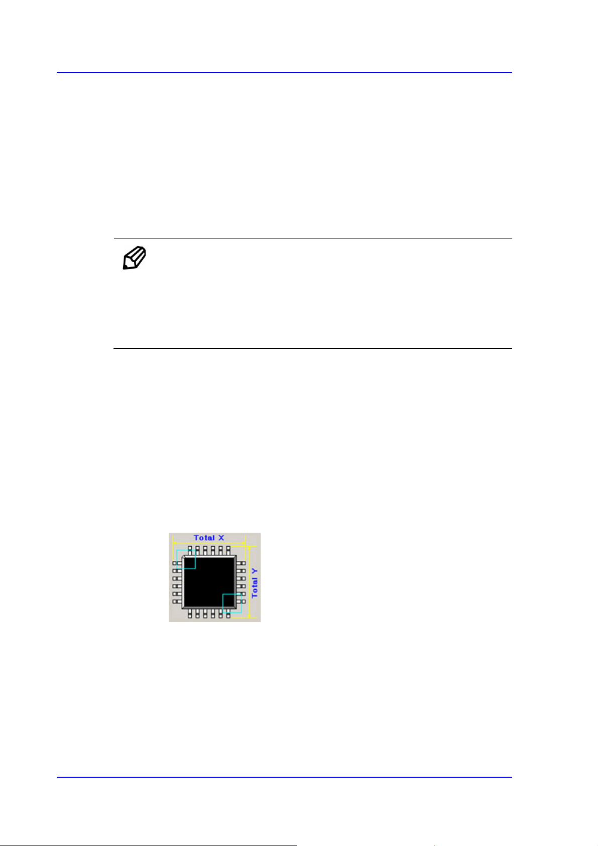
<MFOV Type> Select Box
In the case of a large part that cannot be recognized at a time using the fix camera,
the vision system performs split recognition several times.
Selectable types of split recognition are as follows:
None
Selected when not using the 'Split Recognition ' function (MFOV).
Cross 2P
Used for QFP and PLCC types, Selected when recognizing the part twice in
the diagonal direction of the part.
7-55
Part Registration
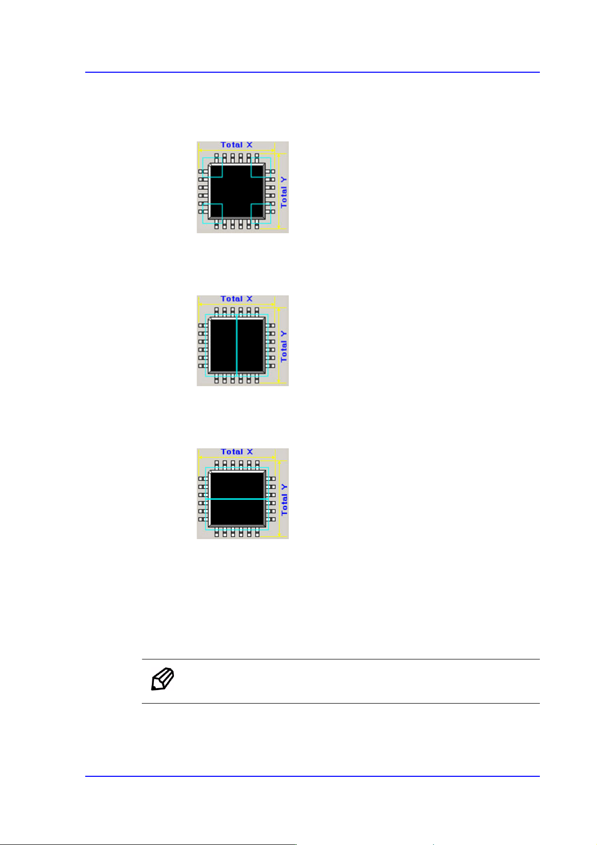
Cross 4P
Used for QFP and PLCC types, Selected when recognizing the part four times
in both the diagonal directions of the part.
Linear H
Used for connectors. Checks the left and right surfaces twice in the horizontal
direction.
Linear V
Used for connectors. Checks the upper and lower surfaces twice in the vertical
direction.
<MFOV Length (mm)> View Field
Inputs the distance through which the head is to move for split recognition.
<Heat Sink> check box
Selected when a radiator is attached on the part body. If this function is selected,
when there are more than two upper leads, only the lower lead is recognized
without recognizing the upper leads.
Memo This 'Heat Sink' function is applied only to TR and small SOP.