SM482PLUS_Admin(Eng_Ver2.8).pdf - 第360页
13-12 Multi-Functional Placer SM482( L) PLUS Administrator’s Guide specific head is recognized. Select the corresponding head from the <Device> combo box. Camera Error Selected when looking at the imag e of part …
13-11
Production Setup
<Inhibit Lane> group
When it is not used, select the workstation. Then the PCB is not loaded on the
corresponding workstation.
<Progressive Product> Check Box
This is a function that uses the docking cart to work on two boards in a sequence if
there isn’t a sufficient number of feeders to produce boards at the optimal productivity.
This function is only supported for the single conveyor option.
Setting this option will first mount at the placement point for JOB A after the board is
loaded and then mount at the placement point for JOB B after replacing the docking
cart. This process is repeated each time a sheet of PCB is being produced.
<Detail> button
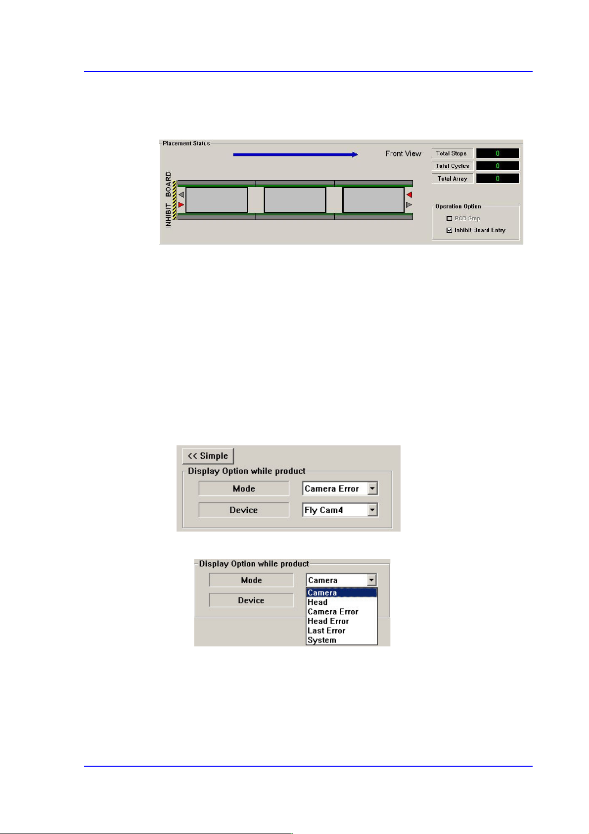
<Display Option while product> group
This button is used to select the image viewed in the SMVision window during
PCB production.
<Mode> combo box
Camera
Selected when looking at the image of a specific camera. Select the
corresponding camera from the <Device> combo box.
Head
Selected when looking at the image in which the part picked up by a

13-12
Multi-Functional Placer SM482(L) PLUS Administrator’s Guide
specific head is recognized. Select the corresponding head from the
<Device> combo box.
Camera Error
Selected when looking at the image of part recognition error from a
specific camera.
It shows the recognized part image according to the placement order
during placement. However, if the placement is completed, the camera
selected in the following <Device> combo box shows the part image error
that occurred last.
Head Error
Selected when looking at the recognition error image of part picked up by
a specific head.
It shows the recognized part image according to the placement order
during placement. However, if the placement is completed, it shows the
image of part recognition error that occurred last among the parts placed
by the head selected in the following <Device> combo box.
Last Error
It shows the recognized part image according to the placement order
during placement. However, if the placement is completed, it shows the
image of part recognition error that occurred last during placement.
System
Shows the part recognition image according to the placement order.
13-13
Production Setup
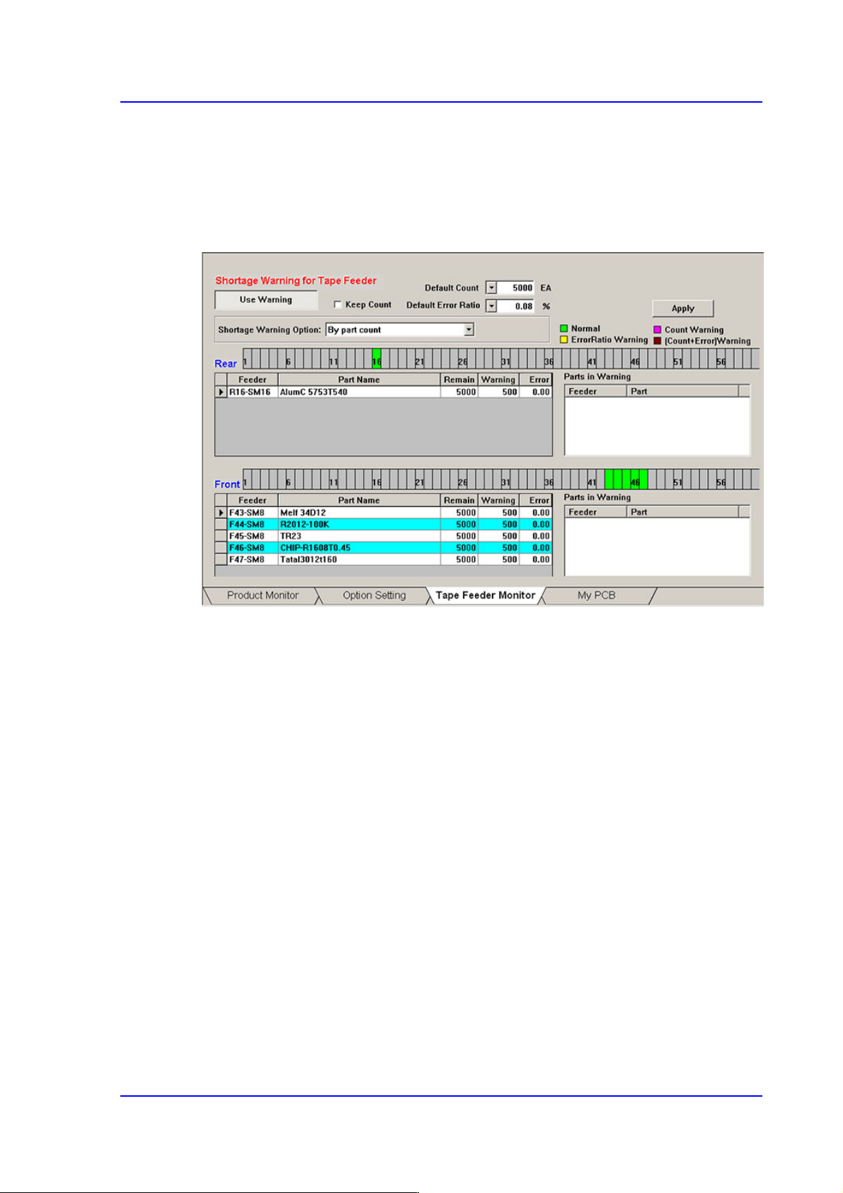
13.1.3. Tape Feeder Monitor
Sets the quantity of remaining components. It shows the remaining components of the
installed tape feeder and alarms against the component shortage. Able to monitor the
errors related with parts supply of tape feeder.
Figure13.5 “Tape Feeder Monitor” tab dialog
<Use Warning> button
Selects whether to automatically show the alarm message setup in the ‘Tape Feeder
Monitor’ tap dialog box while working. It is setup as ‘use’ in the above dialog box.
<Keep Count> check box
Generally, if the PCB program is downloaded, the remaining quantity is set up to the
default count.
In case the same PCB program must be downloaded again for a particular reason
during operation, select this check box to maintain the Remain Count of the tape
feeder installed already.