SM482PLUS_Admin(Eng_Ver2.8).pdf - 第289页
9-1 Step Programming Chapter9. Step Programming The ‘Step’ submenu edits data on PCB plac ement points, component fiducial marks, components to be placed, component suppl ying feeders, and nozzles to pick up components. …
8-36
Multi-Functional Placer SM482(L) PLUS Administrator’s Guide
<Current Pocket> group
<X>: Set the pocket number of the tray to move to or pick up from in X direction.
<Y>: Set the pocket number of the tray to move to or pick up from in Y direction.
<Install to Feeder Base> group
Displays the feeder base unit and slot number when the tray unit is set to the feeder
base.
<Feeder Base>
Designates the feeder base where the stick feeder is to be installed.
0: Not installed on any feeder base.
1: Installed on Feeder Base1(Front Feeder Base).
2: Installed on Feeder Base2(Rear Feeder Base).
<Slot No.>
Displays the number of the feeder base slot in which the corresponding tray unit is
installed currently. The numbers displayed are as follows.
0: Not installed in any slot.
1 - 52: Installed in the corresponding number slot.
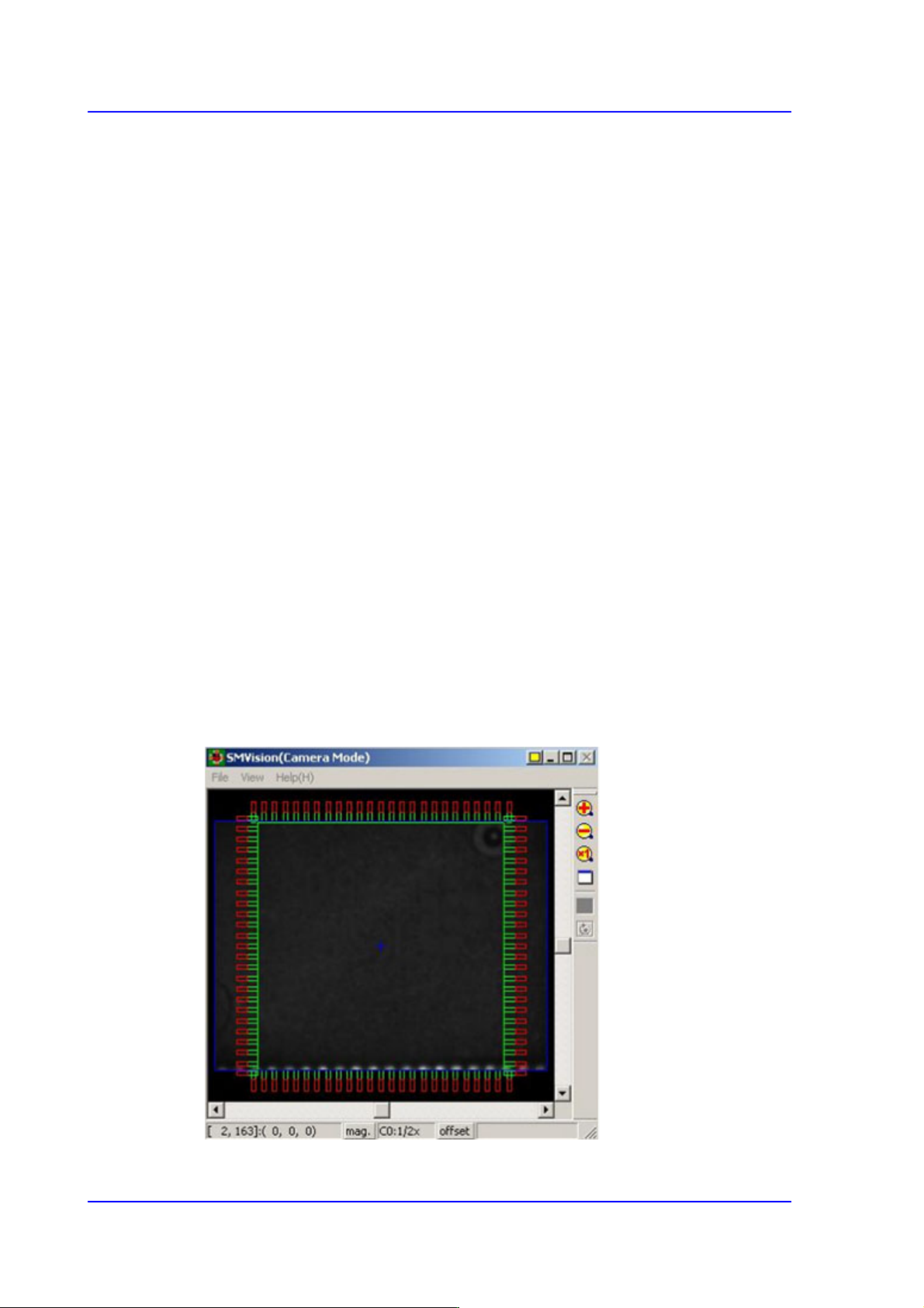
<Part Outline> check box
If this check box is selected, when the fiducial camera is moved to the position of the
corresponding feeder to check the pickup position, the outline image that considers the
angle at which the corresponding part is picked up is displayed on the SMVision
window.
9-1
Step Programming
Chapter9. Step Programming
The ‘Step’ submenu edits data on PCB placement points, component fiducial marks,
components to be placed, component supplying feeders, and nozzles to pick up
components.
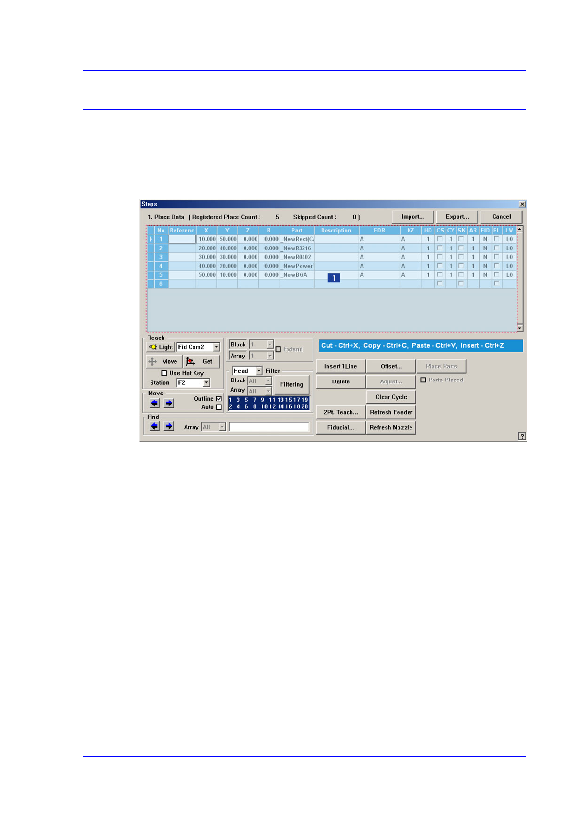
Figure9.1 “Steps” dialog box
1: Grid
‘Grid’ group
Set the edit data related to placement.
<No> column
Refers to the number of the placement point.
<Reference> column
Set the reference name of the placement point. In general, enter the value of R1,
R2, C1, and C2 on the PCB (up to 8 characters).
<X> column
Set the X position of the placement point.
<Y> column
Set the Y position of the placement point.
<Z> column
Set the Z position of the placement point.
9-2
Multi-Functional Placer SM482(L) PLUS Administrator’s Guide
<R> column
Set the R position (rotation angle of the placement component) of the placement
position.
<Part> column
Select the component to place.
<Description> column
Note that slot to display the description of installed components.
<FDR> column
Select the feeder to supply the component.
<NZ> column
Select the nozzle to pick up the component.
<HD> column
Selects the head to pick up the part to be placed.
<CS> column
When you want to start a new cycle, check this check box.
<CY> column
When <Cycle> is clicked on, the corresponding cycle number is displayed.
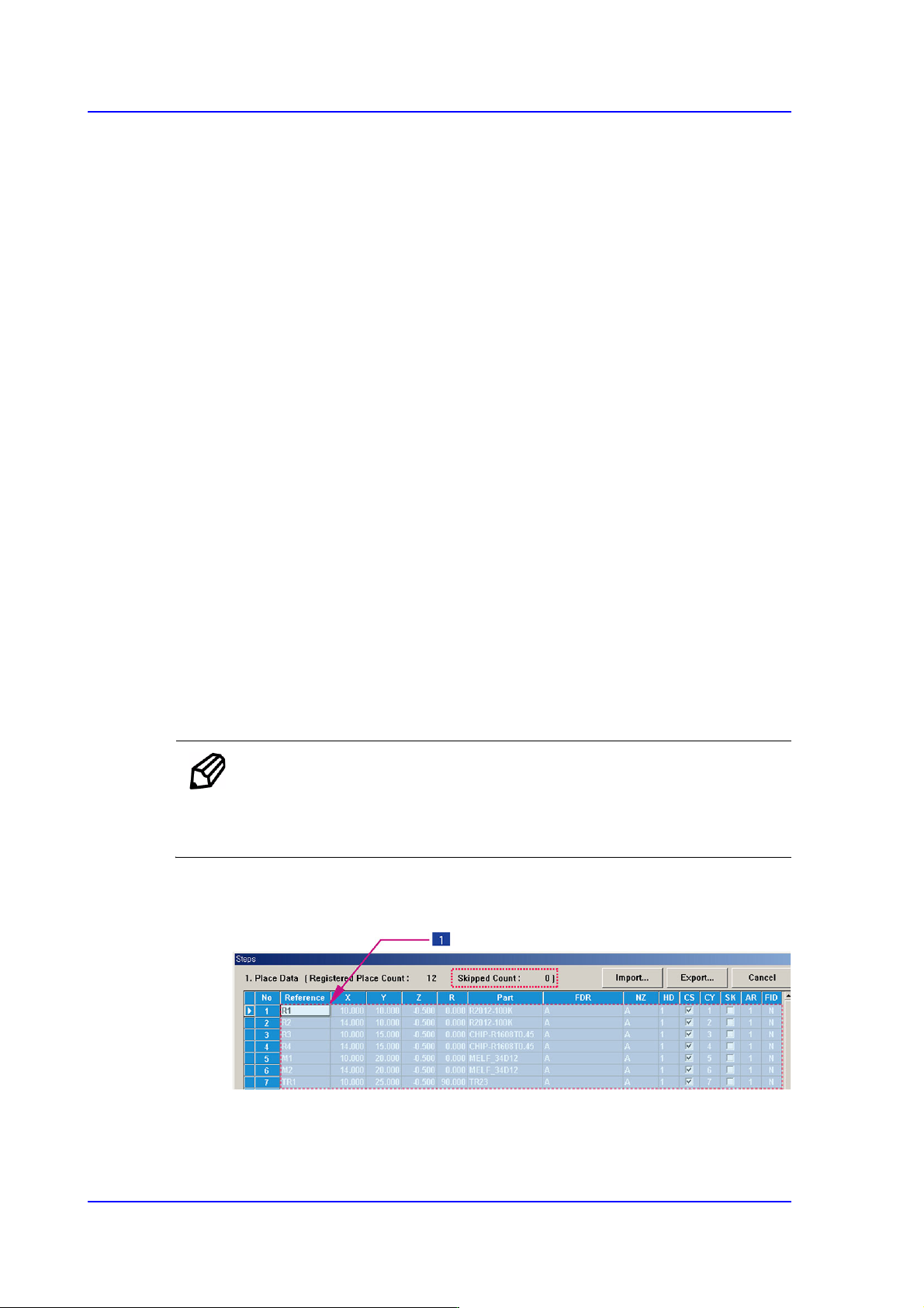
<SK> column
Check the check box when you want to skip the placement point. The number of
skipped rows is indicated in the ‘Skipped Count’.
Memo The part set to be skipped is not included in the number of parts that
can be placed. (The maximum number of parts that can be placed is
150.)
Possible to skip the selected lines after selecting the lines to be skipped with the
mouse. On the contrary, it is possible to setup so as not to skip.
1: Selection of drag using mouse
Select lines using mouse. (Use the mouse drag function.)